Showing posts with label Train set. Show all posts

Sunday, 24 April 2016

Print a wall

Joshua's train set is getting regular use, but he's keen for it to look more realistic - which means finding ways to hide the plywood and gaping holes between the levels. There's a lot of board to cover, and very specific size gaps to fill, so the Scalescenes retaining wall and tunnel mouth kits seemed the best option - as being economic and flexible. I printed out a couple of copies of each, bought a sheet of mounting card, and made a start at the front of the layout where the tracks pass by the high level station.


The Scalescenes prints give an excellent finish - the colouring and detail is spot on. I used a laser printer which I think gives a more robust (damp and light proof) finish, albeit slightly shiny - though a coat of matt varnish could address that. However what you really get is a kit to make a kit - the print-outs need sticking to card and carefully cutting out before even starting assembly. This all takes time, is rather fiddly - and I'm never sure what glue to use. PVA can cause wrinkling, so I use Pritt-Stick on the sheets of paper - but it really isn't very sticky and can lift at the edges.


The benefit is the freedom to adapt the kits. For example the set-track curves and track spacing, combined with the overhang of modern coaches like this Voyager, meant the tunnel openings had to be much wider than any of the suggested shapes. No problem - though I was running out of space to fit a large enough opening, so it is rather tight...


At the other end the loop off the inner track cuts acutely under the station, making a very tricky spot to present realistically. I found some Wills vari-girder mouldings in the bits box, which made up a suitable looking beam. Supports, walls, and parapets were made up to fit and dressed with the Scalescenes prints to match the walls. The result works well, although the Voyager won't clear that innermost track!


Thus the front of the layout looks much more realistic and is a good spot to watch trains go by. Now this is a train-set and is to be played with, so I haven't taken as much care in places that I could of to get edges sharp and disguise paper and card corners. However it's still taken me a good few weeks, on and off, to complete this 4-foot long wall and three tunnel openings, but there's a lot more of the layout needing walls and three more tunnels. I think I'm going to have to think of some short-cuts!

Monday, 21 December 2015

The Night Mail

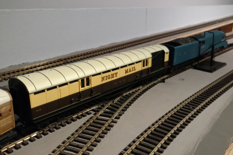
Recently it was my Son's Birthday. He's been asking for the Mallard for some time, so despite being surprisingly tricky to find right now (it had to be blue, apparently) we managed to get him one. While ordering I discovered Hornby still do the Night Mail coach. Now when I was a kid I remember playing with one at a friends, thinking it was so cool, but never got one myself - so I had to get my son one!


This is based on the mail coaches that used to run along the main-lines, picking up mail, sorting it, and dropping it off all without stopping, speeding through the night. That sounds exciting, but the reason I'd thought it so cool was that it operates; it is supplied with some small red mail-bags, a track-side hook and reception bin. Ramps fixed in the track actuate levers under the coach causing it to grab the mail-bad from the hook with a plastic "net", and drop it in the reception bin with another plastic "net".


Well as I can't show that with photos, for the first time on this blog, let's try a video:


All great fun - and yes my Son likes it too! 

Not much actual modelling to report recently - the run up to Christmas always seems so hectic. So Happy Christmas, and back to modelling in the new year! 

Saturday, 1 August 2015

First Steps


Manning the 009 society stand at Amberley the idea was to do some modelling as a demonstration. However rather than have him spend hours on his DS I thought I'd take some projects along for my son to have a go at too. First up was this signal box from a Metcalf kit, which had come with a Railway Modeller a while back.


Joshua loved putting it together, though I did end up helping with the cutting out, and glue spreading... still, he did a good job, and was desperate to build something else. So we moved on to a simple plastic kit for a platelayer's hut (Ratio I think). Again I helped - mostly cleaning up the parts where they'd been cut from the sprue, and holding the parts while Joshua glued them. He was impressed with the speed it went together using liquid solvent, and can't wait to have a go at painting it.


Both buildings have now been positioned on his train set, next we'll have to have a go at making brick retaining walls and tunnels I think.

Friday, 13 February 2015

Train Set Features

I thought I'd post a few more pictures of my Son's train set, last seen when I'd just finished the track-laying and wiring. The few buildings so far are Hornby, most of which came from my childhood train-set, they are nice and robust which is ideal for this situation. They are stuck to the board with impact adhesive for when the board is folded up.


A busy view with some favourite trains on view! Lots of brick walling will be needed.


I found my old car transporter wagon and loading ramp, which adds a bit of fun.


Joshua got given a PECO turntable for his Birthday, so we spent a little time putting the kit together. I'd left enough space for it, so it was simply a case of mark out the circle and cut out with a jig-saw.


The kit is easy enough to assemble, so soon it was in place and having the tracks laid. The turn-table track takes it's power from the approach track, but I have yet to power the spur tracks - I'm sure there is a clever way to power them from the turntable position but I'll probably use a rotary switch.


Finally - in use! That track to the right needs a bridge now...

Monday, 22 December 2014

Knobs and Switches

It struck me that in order to run trains from either oval to the station, and to be able to shunt the station while running trains on the main lines, the wiring for this train set was way beyond connecting a controller to each circuit! I decided I'd better allow for three controllers, even if two would suffice most of the time, which meant having to have rotary switches rather than just 2-way. I settled on 4 main sections that can be switched to any controller, and 7 sub-sections that allow locos to be isolated. Hopefully the control panels make this all clear, and it will allow enough flexibility in operation.


I made up two control panels by printing out a schematic drawn in MS Word. These were mounted on some thick plastic sheet I'd picked up somewhere, then covered in sticky-back plastic (very Blue Peter!). I'd already drilled holes for the switches so they could be fitted, then I wired the switches to a loom ending in a screw terminal "choc-block" before fitting the panels to the layout.


The panels are fitted into the side of the station board, the plywood being cut away to clear the switches and allow the wiring through. The Gaugemaster controller in the middle provides controllers A and B.


With the screw connectors stuck in place (hot glue works well for this) wires are run to the relevant tracks on the layout, and the "temporary" connections of the two circuits to the controllers changed to the switched arrangement.


Further screw terminal blocks were used on each board and wires run from the feed rails to them, via small holes next to the rail, then they were connected back to the blocks by each panel. As the boards are permanently joined I haven't bothered with connectors, though the cables could be released from the terminal blocks if needed, provided they were labelled to aid re-connection! As you can see different coloured wires are used to help identification, it certainly makes wiring up easier. For example I used:

  • Blue: Common return (all outside rails)
  • Red: Main switched sections
  • Orange or Yellow (when I ran out): sub or isolating sections
Plus whatever other colours I had to hand for the controller feeds.


Another block connects the panels to the controllers, and joins all the "common returns" which greatly simplifies the wiring. There is a sticky label by each terminal block with wire codes marked on. The DIN plug on the left is connecting the third controller (C) to a 5-pin DIN socket.


As I've used the same socket as on my other (more serious) layouts, and connected the 16V AC from the Gaugemaster controller, I can use one of my usual hand-held controllers, such as this AMR example (left). However I've also wired a plug to the end of an old Hornby controller, which works surprisingly well. Either way the third controller can be used by someone outside the layout, so friends (and visiting grown ups) can operate without having to squeeze into the centre well.

So after a little planning and careful wiring, I was pleased when the layout worked first time. Even better my Son is very happy, he got the hang of the somewhat complex control knobs quite quickly, and he enjoys running trains in and out of the station from the main line. He's also enjoying shunting the goods sidings!

Sunday, 14 December 2014

Track Pins

I'm a bit behind with the story of my son's train set, so let me finish the tale of track-laying. Of course it wasn't long after half-term I was being pestered to create the upper station. 


These are the tools I use: pliers and small hammer for the pins, the end-cutters and screwdriver are useful for levering out pins when required. The scalpel is for trimming sleepers and slicing off the "chairs" to let the rail joiners fit. The orange-handled cutters on the left are Xuron track cutters, for years I used a slitting disk in a mini-drill which is certainly effective but the trac cutters are quicker and quieter. A fine file is used to clean up the rail end.


Talking of track pins, here's a comparison. At the centre are PECO pins, long and thin and frankly useless. They only really work with "Sundeala board" which is basically compressed paper, sags, disintegrates, and is generally useless as a baseboard top. Even then you need to drill the sleepers with a 0.5mm bit - never mind tedious you'll be forever breaking bits too! If you use set-track you'll find the pre-drilled holes too big. Also they often protrude through the baseboard, ready to slice fingers and knuckles! The bent pin tells it all - these area fast route to frustration.

So for years I've preferred Hornby pins (top left), these are strong enough to be hammered into most baseboard surfaces (including ply) without a pre-drilled hole, and are a tight fit in set-track pin holes. They will go through a sleeper too, though pre-drilling is probably a better idea I rarely bother. The head is bigger and more visible, but when laying track on a "serious" layout I glue it, adding pins around the rails and sleepers to hold it, and pull them out afterwards. So many of these Hornby pins have been used several times already!

When I was running low I popped into Gaugemaster (fortuitously quite local to us) to get more Hornby pins, but saw that Gaugemaster sell their own variant (GM66 if you are interested). These are very similar to the Hornby ones but with a flatter head, and you get more in a pack for similar money. They do a "PECO" style of pin too, but these shorter ones are the ones I'd recommend!


Anyway here's the finished track layout, with platforms being fitted for the upper station. The next task was to wire it all up!

Tuesday, 25 November 2014

The Train Set Runs!

I promised a picture of the board in the folded-away position, so here it is!


The protrusion into the room is quite small - around 12", and doesn't block the window. There's space for some storage underneath too, though admittedly it isn't pretty! The black strips you can see are foam pipe lagging, to soften the blow when crawling under the layout and coming up too soon!


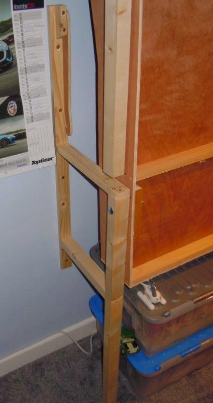
This is a close-up of the rear leg and the frame that holds it off the wall, the pivot bolt can be seen. Above it the front leg hangs, and in this picture the safety catch is not in use!


So base-board done there was pressure to lay some track! First the board was painted grey (with emulsion tester pots) where the track was to go, realistically ballasting isn't going to be high on the priority list but a grey base looks better than plywood. The end curves are 2nd and 3rd radius set-track and the points to the inner "loop" line are Hornby set-track, but the crossover and the branch to the upper level use Peco Streamline, and the straights are flexi-track.


There's no 3rd radius set-track point (a major omission I think), so I used a 2' radius streamline point which is a little larger in radius but flows well. The transition between point and straight, and the inner track at this location, were laid in flexi-track to match. Laying flexi-track and streamline points takes more work - trimming sleepers and carefully lining up the rails - but the result looks better and runs well too.

Much of the track came from my train-set around the loft of my parents house, it has since spent many years in their shed too, so was well tarnished, nothing would run on it. Some vigorous cleaning with a track rubber and fibreglass pencil brought back the shine and (more importantly) the electrical conductivity.

That last photo also shows the Gaugemaster double-controller set under the upper level. I wired one control to the inner track and the other to the outer track, and so we (just) had trains running by half-term!

Friday, 21 November 2014

Installing the baseboard

With the baseboards made it was time to assemble them together. This is not a portable layout, so they were clamped together then big screws used to fix them. I guess it could come apart in the future, though I won't be worrying about splitting track or wiring at baseboard joins as that would significantly complicate things. The front and rear profiles were cut from two pieces of ply, and screwed in place spanning the board joins, hopefully making the whole thing rigid.

The next trick is to pivot the board to the wall. I made up a simple frame for each rear corner: a batten screwed to the wall with a weight-bearing leg spaced away from the wall about a foot. It is this leg that the layout is bolted to with 10 mm bolts and locking nuts. The front corners simply have a leg attached also with a single bolt, so they fold down the side of the layout as it goes vertical.


The layout down, the wall-battens can be seen against the wall but they don't carry the weight of the layout. The double-deck front part of the layout adds to the strength. Underneath the layout the step/box I made recently can be seen, allowing children to operate the layout and see what they are doing, as the lower track is about 3' from the ground.


A close-up of one of the hinged bolts, which is set about 10" into the layout. The leg is in the foreground, the wall batten can be seen behind.


I forgot to take a picture of the layout stored upright, and now I'm not allowed to put it away (!), but as stowed the board is allowed to go slightly past the vertical so it gently leans on the wall. A pair of risers on the side of the layout, topped with a piece of felt to prevent marking, rest against the wall. The main weight of the layout goes down the rear legs, but enough weight is over-centre pushing against the wall to mean it isn't going to fall down.


Nonetheless, just to make sure, a couple of catches are fitted to the wall battens. This simply pivot onto a protruding screw head at the side of the layout, and mean it cannot be pulled down.


I left a cut-out under the rear of the front station board, where the station will be at a high level, and fitted a shelf. My old Gaugemaster "D" controller, which my Dad bought me for my train-set when I was a kid, fits nicely into the gap. It is secured with some wood strips all round and above, and a couple of large washers. When the layout is stowed upright this is pointing down, so the washers are pretty vital!

Monday, 10 November 2014

Trainset Mk 2

A few years ago I built a train set for my son, which folded to go under his bed. We moved house last year and in the summer I redecorated his new bedroom, and we got him a new bed - which didn't allow for the storage of the layout. In any case he was growing out of the simple train set, and it had some limitations including an over-tight curve on the inner track, so I had promised him a bigger layout in his new room.

We'd arranged the room so one wall was mostly free, and I figured the best approach would be a board that folded up against the wall. I'd suggested this for my Nephew and the concept (as built by my sister-in-law) seems to work well. I worked out the space available was about 7' 6" long by 4' 6" wide, leaving space to access bed and wardrobes even when the layout was down - which should allow it to stay up overnight. It's also a reasonable size for a layout I thought, so I doodled a few plans which he looked at, thought about, then he gave me his brief:
  • A double track oval for running trains - and including his sister or friends
  • A high-level track, ideally with bridge
  • A big station with lots of platforms
  • Goods sidings
  • A second station
  • A turntable and engine shed
Phew, a demanding customer! Now the space doesn't seem so big. A few more sketches later I had an idea, so tome for a full-size plan to check. Lining paper was laid out and boxes of track dug out the garage:


It's ambitious but seems to work, so I got a couple of 8' x 4' sheets of 9mm Ply. I'd worked out the main board sizes I needed so I could get the timber merchants to cut it, which also meant I could get them in the car! The layout is made of 4 boards: 2 of 4' 7" by 2", one 3' 6" by 21" and one 3' 6" by 14", and all include some aspect of double-levels. Mostly cross-framing is using 2" x 1" timber but ply was used on the more complex sections, with smaller timber for screwed joints. Ply fascias on the outside are considered part of the framing, and the extra depth adds strength, while the double-deck section should add rigidity along the length of the board too.


This took me quite a while, which is when I realised I'd never built a layout this large or complex before! Anyway here are the four boards laid out together, the rising line and upper section are clear. The front and rear fascias have yet to be fitted, as they will be cut in two sections and bridge the gaps between the three boards, adding rigidity. Note that the front has developed a slightly curved frontage to push the middle board out, easing the curve on the rising line and maximising the access hole in the middle.


Monday, 25 August 2014

Upgrading a train set

A weekend visiting family usually means a break from railway modelling. However this time my wife told me to pack my tools! Our 10-year old nephew wanted some scenery on his train set, so it turned out to be three days of modelling...

A while back his Mum had been looking for somewhere to put the railway, including the loft which wasn't suitable, so I sketched an idea for a baseboard that folded down from his bedroom wall. It turns out my sister in law is an excellent carpenter, so next time we visited things were up and running. My nephew has since built some downloaded card models, and laid some roads. Now he'd also been given some buildings and scenic items, plus some extra track.

My first job was to repair a broken lead from the wall-wart transformer to the controller, so out came the soldering iron. Then came the track; a long siding ended in a point and two short spurs, which was not very practical. I suggested a couple of alternative options, my nephew chose both, so we were off to the local model shop to buy another point. As it involved a kick-back siding we got some wire and a switch, so it could be fed from the adjacent track. Also the station needed a platform on a curve, so a Metcalf kit was purchased too.


With the sidings laid and wired, the controllers were screwed down too, then we added some hills in the front corners with some polystyrene and PVA soaked newspaper. The next day we painted them green and added scatter. He'd been given some nylon "static" grass but didn't know what it was for, fortunately I'd brought my static grass applicator, so we added plenty of that too. The platforms took a surprisingly long time over a couple of evenings, the awkward shape didn't help, but the kit is flexible enough to be built to almost any shape.


There remains of course plenty of things that can be added: fences, trees, bushes, backscenes, more buildings, figures, details, etc. That grey circle is to become a pond. However the trainset has progressed to a model railway, and should provide plenty of fun to it's owner. Now my son is asking when we can start building his new trainset...

Monday, 31 December 2012

Train Set Season

You may remember a couple of years ago I built a train-set for my son. He's gained a couple of locos and some wagons, but for a recent birthday we gave him some more track, and also another train set (a second-hand bargain from a show) for Christmas. This means a bit of work adding a second circuit to the board, but this is the season for train sets.

First job was to remove the existing track. It was laid in the garage in November 2010 when the temperature was well below zero, as a result when brought in the house the rails expanded, although the track didn't move the curves had a negative camber! When released the diameter of the oval expanded by about a quarter of an inch. I then had to plane off the no-more-nails type glue, as it hand't worked well, this time I stuck to track pins. Hint: Hornby pins are larger than PECO, but strong enough to go into plywood.

 
The job was made more complex because of the folding board, this means the track needs to be cut at the board joint and soldered to small brass screw heads to ensure secure alignment. Also every rail needs a wire to bridge the gap, laid above the board because of the double-skin board design.


Further complications are that Hornby and PECO have different geometry for their curved points (I was using various points bought cheap at shows or off ebay), and the size of the board didn't allow two standard straights between curve and board joint. This restricted point placement, and meant I couldn't use the power feed tracks - I just wired back to a terminal block connector for easy connection of controllers.

 
This shows the final layout, as you can see I had allowed for the extra tracks when I painted the board, and there was space for the outer platform and siding. I Think I got the maximum number of tracks on for maximum fun! All points are within reach of one side of the board too. With two controllers I can now play with my son!
Posted by Picasa

Tuesday, 7 December 2010

Train Set - Part 2

Although I measured out for a double track, for now I am sticking with the basic oval and siding that comes with the Thomas set. After all, for now Thomas will be the only train! The point is I will be able to add an extra track, and more sidings, later on.

First I painted the track-bed grey with a couple of tester pots from the DIY store (allowing for future track). The track was stuck down with No More Nails (I thought it might be stronger than PVA but it didn't dry clear, PVA would have been better) and pinned, althoug the track pins were reluctant to go through the ply! At the board edges I used a short length of nickel-silver flexi-track, where the rails crossed the joint I put in brass screws both sides, and then soldered the rails to them, then cut the rails. This should make the track robust at the edge and ensure precise alignment, even though it is cosmetically lacking! Each rail then had a wire soldered to it, running over the hinge post to the rail on the other side, ensuring electrical continuity. The photos should make this clear.


The Hornby controller was screwed to the board in one corner and connected up. In the siding I added a re-railer ramp with uncoupler, I'm surprised Hornby don't include these in the train set. I know they are not pretty but for a child they are very useful! A set of Hornby platforms were cut to fit the board joint and the length of the straight and stuck down with a glue gun. I used the small station building as although I have the larger one, it fouls the other end of the platform when the board is folded! I also found a signal box, this and the station came from my parent's loft ... Finally more tester-pots were used to paint the rest of the board a rather un-convincing grass green, I threw some handfuls of scatter onto the wet paint too. Frankly it hasn't worked that well but it is better than bare ply, and this is just a train set! It can all be spruced up over time.

The real test came today, my Son's 4th Birthday. Even with lots of other presents including Playmobil (which needed a surprising amount of assembly!) and Firman Sam toys (which he is mad about), he was really excited when he opened the big parcel of the train set! Then I produced the board and he set to playing trains. In fact I have spent a significant part of the day kneeling on the floor playing with him - apparently I am the Fat Controller! Clearly it has been a big hit.

So does the board work? Well yes, although I really should get some handles to make moving it about easier. As you can see though - it does fit under the bed as intended! It is really easy to unfold and plug the controller in, so can be up and running in a couple of minutes, so mission accomplished!
Posted by Picasa

Monday, 15 November 2010

Train Set - Part 1

With my little boy's 4th birthday coming up we thought it would be nice to get him a train set; a Hornbly Thomas set has been obtained from the bay of e's. However it won't last long being laid on the floor, nor is it likely to get played with often if it is a lot of trouble to set up. Really the track needs to be laid on a board which can be got out when required, but we have no where to store a large enough board.

The plan I came up with is for a folding board that should fit under his bed; it is 5'6" by 4' and folded it is 2'9" by 4' by about 9" deep. The board has to be strong in order to hinge, but not too heavy. I decided to save weight by using a double-skinned design of 34mm x 18mm timber (sold for door jambs) covered in 3mm ply. Yes, 3mm ... it needs lots of bracing (as shown, about 10' of timber was used) but even so the total thickness of ply is half that traditionally used. (Hint, get ply from a local timber merchant, they'll cut it to size which saved me the bother, and meant I could fit it in the car!)

It's not exactly light, but for the size of board it is manageable, and both much lighter and stronger than traditional board designs. As the frame has ply top and bottom it is incredibly strong - it will not twist! The concern was that the 3mm ply may not be thick enough to be leaned on, hence the extra supporting blocks seen in the first photo. In fact I can kneel on the board so it should be fine! A 6mm top would be stronger but of course, heavier ...

The hinges are of the paste-table type from a local hardware store, attached to uprights in the corners of the board, other uprights act as stops. The outer edge of the board is faced in 5mm foamed PVC, which was free from the marketing department at work, offcuts of advertising boards! This fascia reinforces the hinges and stops. The pictures should make it clear.


The last picture shows what could be fitted onto the board. The train set came with (surprisingly) 3rd radius curves, a second radius oval can be fitted inside. The outer oval is positioned to allow a platform to fit on the outside on one side of the board, with a siding outside the oval on the other, obviously plenty of space inside for sidings. There is space for a short straight between the end curve and a length of flexi-track over the board joint, a 6' long board would allow a double-straight (or two points) either side of the joint but that would be too big to fit under the bed. At one end the fascia is raised to allow for a tunnel.
Posted by Picasa