I'd meant to post pictures of the completed trees planted on the layout once they were done, but shortly afterwards I went down with Covid, and I have only now got around to this update!
Since the baseboard is foam-core board and landscape is expanded polystyrene covered in a PVA-soaked tissue and tile grout skin, planting the trees is easy. A dental probe is used to punch a hole through the hard skin of the scenery after which the tree can be "planted", it's wire "root" pushing easily through polystyrene and foam-core. The wire and base of the trunk are coated with matt modge-podge to hold it and if needed gound cover is pushed out the way to allow the trunk to sit on the landscape, any gaps being disguised with a little extra ground foam scatter.
The right-hand end of the layout now looks quite wooded, as is the intention since the river valleys are filled with trees. Although the trees form a row only one tree deep the use of denser foliage on trees in the centre suggest the woodland is more dense than it actually is. One tree sits at the front adding depth to the scene and acting as a view-blocker, while the trees at the right-hand end very effectively screen the track exit. With the tree at the front too, the exit is not easily visible even looking along the layout.
You may notice some flowers and grass tufts have been added, the flowers adding a welcome splash of coulour but hopefully in a subtle way while the tufts add more variety to the grassy areas.
At the left hand end a couple of large trees break up the scene and help disguise the compressed road, the tree at the rear having more dense foliage. I added some commercial poplar trees behind the station where there is a narrow embankment, hopefully adding some visual interest.
The playground is now fully assembled and set into the scene, and backed by trees to give a woodland effect. It has gained a fence (Ratio) and some gates. The rear fence is attached to the playground sub-base while at the front it is fixed to the embankment, which along with the low undergrowth completely disguises the edge of the sub-base. The playground surface has a brown scatter representing the bark chippings that once seemed popular for such playgrounds. Some flowers (pansies?) line the embankment and there appear to be some bluebells in the woods.
At the right-hand end the trees can be seen to hide the exit track, while the tree at the front frames a scene around the bridge. My wife observed that the tree at the front has become a regular feature of my layouts, including Loctern Quay and Awngate! At the rear a tree by the stream both disguises the join in the backscene and casts a shadow where the stream meets the backscene. Grass tufts can be seen in the fields too.
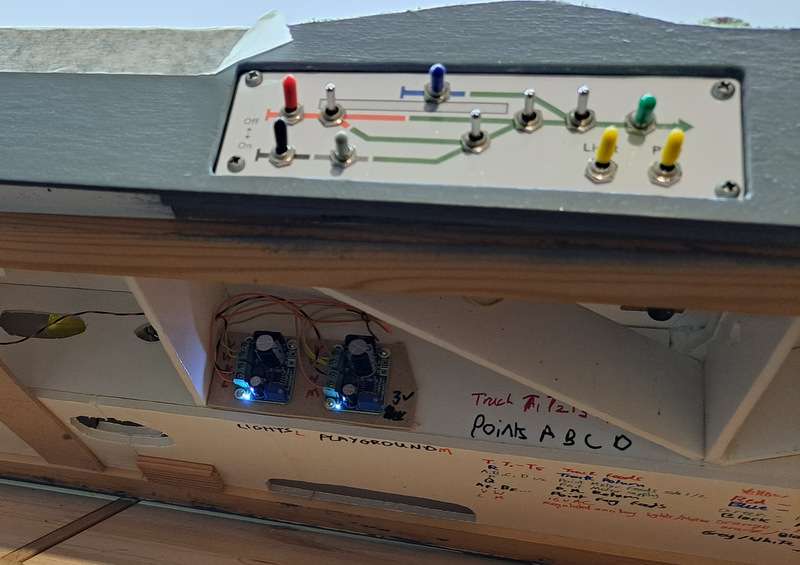
The last stage of the animated playground construction is to wire it into the layout, with a switch so it is easily started and stopped. There was space on the control panel, so I edited the Word file I'd created it in to add a couple more switches.
I actually create two copies of the panel, one has outlines of the switch positions to ensure the design allows for the space they need and when printed out marks where to drill the hole, the other is the printout that is used for the panel. The playground switch has been added bottom right marked "play", you can see I have also added a switch for lighting as I plan to add platform lamps at some point. The holes in the paper were opened out with a scalpel after placing over the drilled aluminium panel (see below...)
The existing panel was removed from the layout and all the switches were removed, the clear plastic front and existing print-out taken off. 6mm holes were drilled in the aluminium panel for the new switches. This is the rear, upside-down (i.e. flipped over towards the camera) so the "light" and "play" switches are top-right, the sharpie labels help me remember which switch goes where. Just above the switch hole (so below in the photo) is a 2mm hole about 1mm deep used to locate the "tab" on the switch washer, this stops the switches rotating in the hole.
With the new printout placed on the aluminium and the clear plastic over the top, the track switches were reinserted, then the holes for the new switches opened out through the plastic with a scalpel before fitting the new switches in place. Since point motor switches are bare metal and the only colour caps I had in that didn't match colours already in use were yellow, the new switches have yellow caps!
The playground motors are fed via a voltage regulator, these little circuit boards output controlled DC from a range of AC or DC inputs, and are cheaply available on ebay (something like this although I've had these in a while). In this case the input uses 16V AC which is provided from my transformer packs to the layout though the 6-pin DIN connection I have standardised on, removing the need for additional specialist power supplies, and the screw potentiometer is adjusted to give about 3V. The output from the regulator goes to the two motors via the panel switch - simple. While at it I put a second regulator in for the future lighting, which can be set to a different voltage. The regulators attached with some tiny screws to an offcut of MDF glued to the foam-core baseboard.
I attached a choc-block connector to the underside of the playground sub-base with hot glue and wired the motors to it - there are enough connectors to allow a resister to be added to either motor if ever needed. The playground can then be removed by unscrewing the terminals to the two orange wires.
That's all the practical work done, I just need to finish the playground scenically now.
When I was a kid, I did like a roundabout. Maybe it was the sensation of speed, maybe because it didn't matter if there was a group of kids or just yourself. Since a roundabout should be the easiest play equipment to animate I thought I would add one, but the Gaugemaster kit didn't include one. There was a spinning thing kids can hang from, but I wanted a traditional ground-level roundabout. This was built from scrap parts and my imagination.
The basis is a large gear with the teeth cut off, this was attached to a shaft, put in the Dremel, and while spinning a file applied gently to ensure the edge was round and smooth. I then drilled small holes near the edge 90 degrees apart.
A length of tube was opened out to slide over the projecting shaft, and at the top four notches cut. Four handrails were added upright from the holes and across into the centre-post notches (two are L-shape and one is an inverted U-shape running right across). The wire was later blackened.
The centre post was topped with a plastic disc cut from a leather punch. I also added a seat onto the gear boss, this would have been easier before fitting the handrails! 20 thou plastic was cut to the circular shape and the centre punched out, then cut into two semi-circular pieces which were glued around the centre-post sitting on the boss. I also raised the ground around the roundabout with a piece of 40 thou plastic to disguise the depth of the roundabout.
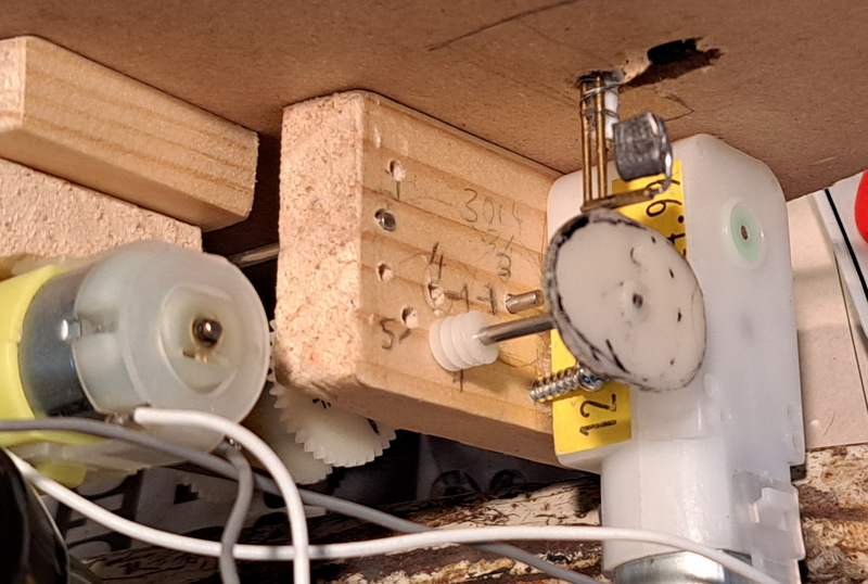
The roundabout is simply motorised with it's own motor/gearbox, mounted on a couple of blocks of wood, the lower is a spacer for the motor output drive, the upper has a 2mm hole through which the shaft passes to keep it vertical.
The animated playground equipment fitted to the sub-base in place on the layout, the motors and mechanism are hidden within the layout. The foam-core board construction of the layout means there is no access to the motors and mechanism from below, so the sub-base needs to remain removeable in case of maintenance.
The animation may be a little jerky but it works surprisingly well, although the motors are really quite noisy.
The Gaugemaster/Faller woodland-style playground kit also included a see-saw. It does seem very long, but the style matches the other items in the set and I figured it could also be animated.
I drilled a hole across the centre of the see-saw beam and opened it out to take a short length of the brass tube, and holes were drilled through both sides of the "yoke" to take a piece of wire to provide the pivot. I swapped the 0.7mm brass wire shown with a thicker steel wire from a paperclip for a tighter fit, and all metal was then blackened. As with the swing, the base of the yoke was stuck to a 20 thou plastic base with solvent to provide a firm baseplate.
I decided on a cam drive as this allows a more irregular movement than the sinusoidal motion of a crank, see-saws not having the same regularity of a swing. The assembly looks complex but is actually a bit of a bodge:
The actuating rod is bent up from a paperclip, at the top it bends into a hole in the back of the see-saw. The hole is oversize to allow the arc movement of the hole relative to the rod.
The short horizontal section at the top of the rod is partly as I found I needed to increase movement, and partly to allow some adjustment of see-saw position
The actuating rod passes through the base and then a short section of brass tube (it was quite a tight fit so a long section might bind), this is fitted into a longer plastic tube which is glued to the base. This join was later reinforced
The rod then bends 90 degrees to run horizontally through parallel fixed rods, this prevents the actuating rod rotating. The fixed rods are secured to the plastic tube with wire wrapped around
The actuating rod then bends again to pass over the cam, a length of brass tube acts as a roller, and is held in place by another bend in the rod
The cam is cut from a large gear, and raises the see-saw twice per revelation, with a deliberately irregular profile. This is driven from the same gear train that drives the swing but at the other end of the assembly seen in the last post, the cam rotates in about 5-6 seconds. The tail end of the actuating rod beyond the cam roller had a piece of lead clamped on to help ensure the see-saw dropped, I had considered a spring but this seems to work.
The video provides evidence that this Heath-Robinson arrangement actually seems to work!
Hexworthy represents the terminus of a preserved railway, and should have the facilities of one, which often include a kids' playground. I had left space and a removable base for this at the end of the car park behind the station. After looking at what was available I settled on this plastic kit marketed by Gaugemaster as OO, although it's actually a Faller HO scale kit. To be fair, there's little visible difference in the size of the play equipment.
Now the thing is I thought a static playground would look a bit dull. This might be a daft idea, but I wanted movement in the playground. I was inspired by the book "Industrial and mechanised modelling" by Dave Rowe in which a number of animated layout features are described, including a swing hung from a tree branch.
I started with the swing, partly because it looked tricky. I replaced the top bar with one cut from plastic tube into which a brass tube fitted perfectly, and was able to rotate within it. I had thought of using a brass outer tube too but I had to cut slots in it for the swing "ropes" which would be much more difficult in brass, and because plastic could be attached to the supports with solvent.
I cut grooves across the brass tube so I could drill them for the "ropes", which are 0.5mm wire and soldered into the tube (it's easier to drill in a groove than the outside of a cylinder). The end of the tube had a piece of brass fret with a hole in one end soldered on as a crank. The brass tube slots into the plastic tube and is able to rotate with the swing ropes moving through an arc via the lateral slots. A small piece of microstrip across one of the lateral slots prevents the assembly coming back out. Similar wire "ropes" for the static swing (one moving is enough!) were glued into holes in the plastic tube, the wires and crank were blackened and swing seats were then added from plasticard.
The swing supports are from the kit and assembled with the replacement top bar, the moving swing is operated by the crank on the end of the top bar. The easiest way to fix the uprights rigidly was to glue to a plastic base with solvent, the base is attached to the wooden playground base with contact adhesive. Another brass tube is superglued up the rear support through which passes a blackened springy steel wire, after a flexible arc this passes through the hole in the crank. Moving this wire up and down through the tube moves the swing, the arc and springiness of the wire (it might be a guitar string or left over from wire-in-tube point control) allows for the crank hole movement being an arc rather than linear.
I had toyed with the idea of using servos driven by a Raspberry Pi, Pico, or similar microprocessor. This approach would have great potential here and might simplify the drive, but would be a whole new area of learning for me and could become a bit of a rabbit hole. Plus, I had a couple of cheap motors with gearboxes and a load of gears and shafts - the gears left over from motorising the turntable on Southon Yard. So, here we have a crank arrangement to turn the rotary motion from the motor (seen far left) into sinusoidal linear motion of the operating wire.
The brass arm is pivoted (right) and has a slot made from a loop of 1mm brass wire (left), a track pin moving in a circular motion (attached off-centre to the gear - the teeth are not used) moves the slotted arm up and down. After some experimentation the thinner arm branching off is used to move the wire, the arm has three holes and the wire has a couple of bends to allow adjustment with pliers.
The drive unit is simply made from lengths of timber, quite small section, and designed to fit below the playground sub-base. Here it is seen inverted, the motor is glued in place with a couple of screws to stop any twist, and hangs down into the baseboard void. The arm driving the swing is on the far end. There are gears on the inner of the left side which step down the speed to the crank. With the motors running on 3V the output shaft rotates in 2 seconds, so the gears step down 2:1 for the swing to take 4 seconds, which is what Dave Rowe had calculated for his swing, and seems about right.
My Dremel in its drill stand came in very useful in making the mechanism. I clamped the two pieces of wood together and drilled 2mm holes in two corners. Cut-down shafts were fitted in these ensuring the wood stayed aligned while I drilled the other carefully marked-out holes, the drill stand ensuring they were straight and parallel. The wood pieces were then spaced apart using longer shafts through the corner holes, holes for rotating shafts were opened out slightly. The two wood pieces spaced apart ensure shafts stay aligned and parallel when rotating, allow reducing gears between them, and as will be seen in the next instalment, allow drive to another item a little distance from the swing.