The Gaugemaster/Faller woodland-style playground kit also included a see-saw. It does seem very long, but the style matches the other items in the set and I figured it could also be animated.
I drilled a hole across the centre of the see-saw beam and opened it out to take a short length of the brass tube, and holes were drilled through both sides of the "yoke" to take a piece of wire to provide the pivot. I swapped the 0.7mm brass wire shown with a thicker steel wire from a paperclip for a tighter fit, and all metal was then blackened. As with the swing, the base of the yoke was stuck to a 20 thou plastic base with solvent to provide a firm baseplate.
I decided on a cam drive as this allows a more irregular movement than the sinusoidal motion of a crank, see-saws not having the same regularity of a swing. The assembly looks complex but is actually a bit of a bodge:
The actuating rod is bent up from a paperclip, at the top it bends into a hole in the back of the see-saw. The hole is oversize to allow the arc movement of the hole relative to the rod.
The short horizontal section at the top of the rod is partly as I found I needed to increase movement, and partly to allow some adjustment of see-saw position
The actuating rod passes through the base and then a short section of brass tube (it was quite a tight fit so a long section might bind), this is fitted into a longer plastic tube which is glued to the base. This join was later reinforced
The rod then bends 90 degrees to run horizontally through parallel fixed rods, this prevents the actuating rod rotating. The fixed rods are secured to the plastic tube with wire wrapped around
The actuating rod then bends again to pass over the cam, a length of brass tube acts as a roller, and is held in place by another bend in the rod
The cam is cut from a large gear, and raises the see-saw twice per revelation, with a deliberately irregular profile. This is driven from the same gear train that drives the swing but at the other end of the assembly seen in the last post, the cam rotates in about 5-6 seconds. The tail end of the actuating rod beyond the cam roller had a piece of lead clamped on to help ensure the see-saw dropped, I had considered a spring but this seems to work.
The video provides evidence that this Heath-Robinson arrangement actually seems to work!
Hexworthy represents the terminus of a preserved railway, and should have the facilities of one, which often include a kids' playground. I had left space and a removable base for this at the end of the car park behind the station. After looking at what was available I settled on this plastic kit marketed by Gaugemaster as OO, although it's actually a Faller HO scale kit. To be fair, there's little visible difference in the size of the play equipment.
Now the thing is I thought a static playground would look a bit dull. This might be a daft idea, but I wanted movement in the playground. I was inspired by the book "Industrial and mechanised modelling" by Dave Rowe in which a number of animated layout features are described, including a swing hung from a tree branch.
I started with the swing, partly because it looked tricky. I replaced the top bar with one cut from plastic tube into which a brass tube fitted perfectly, and was able to rotate within it. I had thought of using a brass outer tube too but I had to cut slots in it for the swing "ropes" which would be much more difficult in brass, and because plastic could be attached to the supports with solvent.
I cut grooves across the brass tube so I could drill them for the "ropes", which are 0.5mm wire and soldered into the tube (it's easier to drill in a groove than the outside of a cylinder). The end of the tube had a piece of brass fret with a hole in one end soldered on as a crank. The brass tube slots into the plastic tube and is able to rotate with the swing ropes moving through an arc via the lateral slots. A small piece of microstrip across one of the lateral slots prevents the assembly coming back out. Similar wire "ropes" for the static swing (one moving is enough!) were glued into holes in the plastic tube, the wires and crank were blackened and swing seats were then added from plasticard.
The swing supports are from the kit and assembled with the replacement top bar, the moving swing is operated by the crank on the end of the top bar. The easiest way to fix the uprights rigidly was to glue to a plastic base with solvent, the base is attached to the wooden playground base with contact adhesive. Another brass tube is superglued up the rear support through which passes a blackened springy steel wire, after a flexible arc this passes through the hole in the crank. Moving this wire up and down through the tube moves the swing, the arc and springiness of the wire (it might be a guitar string or left over from wire-in-tube point control) allows for the crank hole movement being an arc rather than linear.
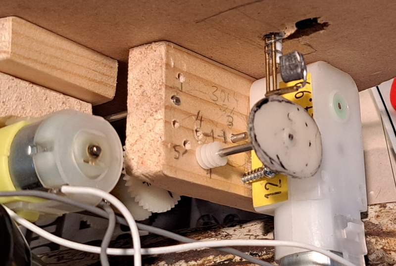
I had toyed with the idea of using servos driven by a Raspberry Pi, Pico, or similar microprocessor. This approach would have great potential here and might simplify the drive, but would be a whole new area of learning for me and could become a bit of a rabbit hole. Plus, I had a couple of cheap motors with gearboxes and a load of gears and shafts - the gears left over from motorising the turntable on Southon Yard. So, here we have a crank arrangement to turn the rotary motion from the motor (seen far left) into sinusoidal linear motion of the operating wire.
The brass arm is pivoted (right) and has a slot made from a loop of 1mm brass wire (left), a track pin moving in a circular motion (attached off-centre to the gear - the teeth are not used) moves the slotted arm up and down. After some experimentation the thinner arm branching off is used to move the wire, the arm has three holes and the wire has a couple of bends to allow adjustment with pliers.
The drive unit is simply made from lengths of timber, quite small section, and designed to fit below the playground sub-base. Here it is seen inverted, the motor is glued in place with a couple of screws to stop any twist, and hangs down into the baseboard void. The arm driving the swing is on the far end. There are gears on the inner of the left side which step down the speed to the crank. With the motors running on 3V the output shaft rotates in 2 seconds, so the gears step down 2:1 for the swing to take 4 seconds, which is what Dave Rowe had calculated for his swing, and seems about right.
My Dremel in its drill stand came in very useful in making the mechanism. I clamped the two pieces of wood together and drilled 2mm holes in two corners. Cut-down shafts were fitted in these ensuring the wood stayed aligned while I drilled the other carefully marked-out holes, the drill stand ensuring they were straight and parallel. The wood pieces were then spaced apart using longer shafts through the corner holes, holes for rotating shafts were opened out slightly. The two wood pieces spaced apart ensure shafts stay aligned and parallel when rotating, allow reducing gears between them, and as will be seen in the next instalment, allow drive to another item a little distance from the swing.
My Christmas present this year is a Victory class 060T, a first ready-to-run model from Planet Industrials.
It's a chunky tank engine, not a small loco but compact and powerful looking, with nice proportions and simple lines. The model is very fine, and surprisingly heavy.
The tidy lines of the loco means it is modest in apparent detail, but look closer and there are lamp irons, brakes and rigging, sprung buffers, and peering into the cab a fully detailed back-head and controls are present and painted too. It is even supplied with a leaflet explaining the origins of the class and where the 12 locos built served.
The couplings are a little droopy, but nothing a tightening of a screw won't fix by the look of it, and as an industrial loco it will need a little weathering as well as coal in the (empty) bunker and a crew. However, the more pressing issue for me is the lack of a layout to run it on. I'm sure I'll get around to addressing that some day.
Happy Christmas, and I hope Santa brought you something nice too!
A few years ago - I've forgotten how many - Bachmann announced they would be making models of the little Hunslet saddle tanks that once worked the slate quarries of Wales, and many of which survive working on preserved lines around the UK. Of course, I wanted one, but the wait has been a long one. In the meantime other models have come - The Ffestiniog England, and Bachmann's own Double Fairlie - but the quarry Hunslets were still elusive. I even put some money aside following the sale of Awngate. Then a couple of weeks ago there were sightings of the first - Britomart must have got the faster boat from China, along with some surprise larger Penrhyn/Ffestiniog Hunslets. Finally, yesterday I saw Gaugemaster had some in stock, so today I went over to have a look. You see, I really couldn't decide between the more practical cabbed version, or the appealingly detailed cabless version...
...so I ended up getting one of each. For me, this is rather extravagant, but they are lovely and will look nice on any 009 layout.
Dorothea has a cab making her more practical for preservation use, and in green will match many of my other locos, although the ones I built are not beautifully lined like this. The prototype now works on the Launceston railway, not so far from Hexworthy.
Nesta is without cab, showing off the delightful detail of the back-head, and looks rather distinctive in lined Penrhyn black. The prototype Nesta works on the Bala Lake Railway.
There is a seam along the cylinders, the couplings could do with replacing with something more discreet, and some gentle weathering would add to the realism (don't worry, they will stay pretty clean), but otherwise they look great and run well too.
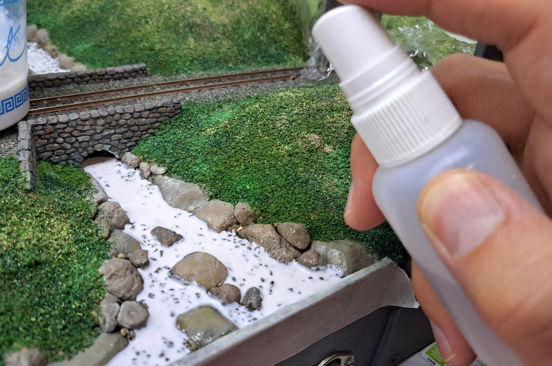
Having experimented with techniques it was time to make a start on the river and stream. I'd chosen to use Modge Podge as it seemed to work well, but would require lots of layers, and a suitable brown tint.
This time I mixed the acrylic paint in a separate jar, a thin watery mix of a colour to match the river in the photos. The paint was added to the Modge Podge (in the yogurt pot) to give it a slight tint and to thin it slightly, maybe 20-30% water/paint in the Modge Podge. The other vital substance is IPA (alcohol) in the spray bottle.
The first layer was applied with a pipette, this could be relatively thick (about 1.5mm to cover the stones, although it will be thinner once dry) since it can dry from both sides, the scenery absorbing the moisture from below. However, there is a slight problem...
It looks like someone put bubble-bath in the river!
Fortunately a couple of sprays of the IPA kills the bubbles. The yogurt pot was then covered with cling film and it was left 2-3 days.
Many coats followed, applied more thinly (0.5mm or so) with a brush, and using a toothpick to push the edges of the "puddle" up to and between the rocks. It can't be applied too thick or it doesn't dry clear, there are a few places where there is a slight cloudiness, though it isn't particularly noticeable.
Every couple of coats I added more Modge Podge to the yogurt pot, and occasionally a little more paint, but though adding more Modge Podge (and possibly a little evaporation despite the cling-film) gradually the mix got thicker and the colour a little weaker.
I lost count of the coats having added a couple a week over several weeks, but it must be at least 10. By now the mixture is thick enough to leave some texture like a burbling stream - well that's what I hope.
So now I think the stream is just about deep enough, and looks pretty good. The colour and opacity seem about right to me, and the surface texture realistic.
The river along the river bank could maybe do with a little extra depth.
I'm thinking of using the Deluxe Materials Aqua Magic as a final layer as the experiments suggested it might have a slightly more gloss finish, and I have it anyway. First though I'm wondering if more texture/ripples should be added.