Showing posts with label Layout plans. Show all posts

Tuesday, 5 May 2026

Whittingly - To Extend or Not?

After my last post considering what next for Whittingly I've pondered on the feedback and the practicalities, and sketched an alternative idea - Plan C? In this case, short 6" extensions are added to both ends of the scene, being fixed extensions to the baseboard where marked with arrows on the plan. That on the left provides the spur beyond the platform canopy and extended hospital buildings, while that on the right extends both loop lines and the engine shed. The overall board length is now 3' 6" which is still easy to store and handle, while a separate fiddle yard need only contain a turntable or sector plate. 


This is difficult to picture in 3D, so thanks to the visualisation possible with CAD (card aided design) using cereal packets, here's a mock up of what this plan might look like. 


At the left-hand end the front track protrudes beyond the platform canopy, providing somewhere for the loco to rest in view. Most of this extension is taken up with the stores building, which would need to be extended from the low-relief building on the existing board - this is likely the most difficult task since brickwork would need to match and I'd rather not lift the existing building. I've not mocked it up but behind this the boiler house roof would need extending too, but there is space for a curved backscene, and perhaps a tall brick chimney? The left hand end could feature a flat/low relief wall of the main hospital building. 


At the right-hand end the two loop tracks are lengthened. The engine shed and its siding would also need extending, the back of the shed just being an open hole against the backscene - and as it is at an angle, it would be difficult to extend. Making the extension in corrugated iron as if a later add-on might make things easier (and more interesting), though matching the roof could still be tricky. In the foreground, I might move the tree to the right (perhaps with a second tree) to hide the exit. There could be space for a footbridge as a view block, although I don't think it is needed. 


This view shows that the lengthened loop lines will allow plenty of clearance to run around 4 wagons or two 6-wheel coaches while they remain on scene. The fiddle yard still completes the run-round loop so the loco must go off-scene; extending the scene to fit a point in adds at least 18" as in Plan B in the last post.


So, this all looks possible, although extending the buildings looks difficult without removing them from the scene, with the resulting ground cover damage to make good. The question is, are these extensions worth the extra effort? The alternative remains Plan A, which effectively has the extended trackwork but in non-scenic areas, and so keeping the original scene unmodified. The scenic extensions of Plan C means that more of the trains are visible more of the time, and the scenic frontage of the layout is increased without increasing the overall length, but operation is unchanged. 

I'm interested in your views!

Friday, 27 March 2026

Whittingly - What next?

Since the Rail200 event at the NEC National Festival or Railway Modelling, Whittingly Hospital has lived in its box in the garage. It was always intended to be the basis of an operational layout, not simply a diorama, so it is time to think about the transition. 


As a reminder, this overhead shot shows the layout as built within the Rail200 rules - which limited not just baseboard size, but overall height and the position of the front, disconnected, through track. The buildings were all constructed to fit within the available footprint and height limit. 


So here is Plan A. This was my original concept. The track layout is modified with a left-hand point by the end of the platform connecting the 3-way point to form a crossover, but otherwise the scenic area is unchanged. I would replace the backscene with a taller one, and add a cameo-style lighting pelmet. 

The key changes would be off-stage. To the left, a short extension gives a little more head shunt room beyond the platform canopy, and lengthens the two sidings through the buildings. On the right, a fiddle yard both provides for a change of train and completes a run-round loop with the 3-way point. I'd sketched a turntable yard, though if that doesn't look like it would work a sector plate would do. A train of 2 6-wheel coaches or 3-4 wagons and loco would be 15-18".

In this plan, the Rail200 challenge entry is kept largely unchanged, which minimises the work involved, and there are no board joins in the scenery. The downside is that only about half the layout length is scenic, shunting will go off-stage, and during key movements such as running around the loco can't be seen. 


Plan B is more ambitious. The extension to the left has become scenic, allowing the loco to be seen beyond the station canopy. A second board to the right provides the rest of the run-round loop and a point "on-stage", as well as the off-stage fiddle yard. This means pretty much all operation will be visible, and makes the scenic length around double that of the fiddle yard. 

The downsides are the complexities of extending the existing buildings. The engine shed would be particularly problematic, as sketched it crosses a board join, but the current structure is well fixed down and has an angled rear that is incomplete. I'm not sure how well the scene on the right-hand board works, messing up the balance of the existing scene without really adding to it. There's also an inconvenient backscene join, and it's harder to store. Finally, the resulting layout has lost the connection to the Rail200 challenge by growing well beyond its original size. While technically better, it would be better not starting from the current layout. 

Let me know what you think!

Tuesday, 11 April 2017

Narrow Gauge to Hexworthy


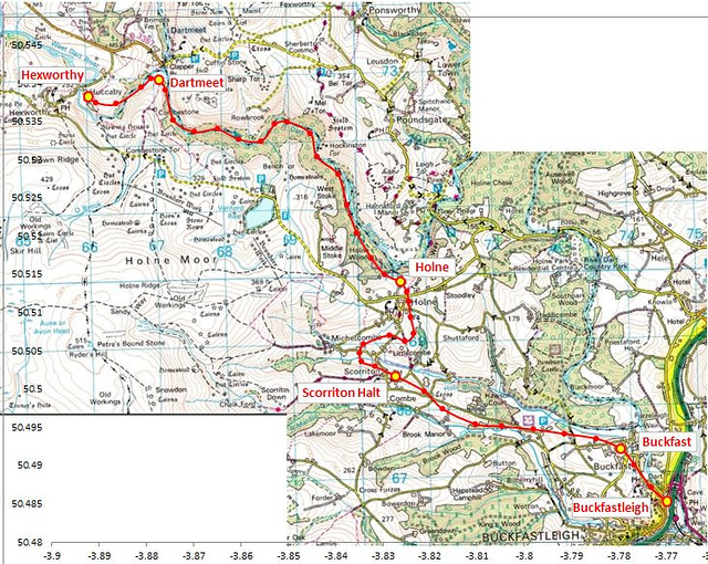
A little while back, I posted about using map data from websites to plan imaginary railways. This was the route I plotted, for a narrow gauge railway running from Buckfastleigh to Hexworthy on Dartmoor.

BuckfastleighToHexworthyOS

There are a number of (long disused) tin mines and some granite workings around Hexworthy, some involved significant works, such as a mill leat that runs for miles across the moor following the contour lines, to power the mine machinery. So it's not unreasonable to suppose that wanting to increase their output in such a remote location, the mine owners got together to promote a railway. The terrain is pretty hard going and the budget was limited, so inspired by developments in North Wales, narrow gauge was chosen and the line opened in the early 1870's.

The railway starts in the yard of the South Devon Railway (later GWR) at Buckfastleigh which had arrived in 1872, where there were a couple of exchange sidings, and immediately starts climbing to reach Buckfast. This is where the sheds and workshops were located, there being more space. From then on the line climbs through open farmland to a halt near Scorriton, and curves over the Holne Brook valley with a small viaduct, before tackling the steepest climb to a deep cutting to reach Holne. This is the main passing station, and the point where the line re-enters the Dart valley. After a short downward stretch the rest of the route follows the valley side, climbing but getting closer to the river below, which is crossed near Dartmeet. A station here serves the main road, and became a popular tourist destination, but the final terminus is the quiet hamlet of Hexworthy, where a spur back across the river serves an incline to the various quarries, high on the moor to the south.

BuckfastleighToHexworthyAltitude

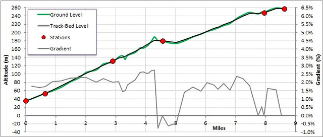
Now Tin was refined at the mines so unlike coal or slate, the outward traffic was low volume, high value. The remote location and the need for coal and stores for the mines, and to support and transport the workforce, made the railway necessary - rather like the Redlake Tramway built a few miles south, years later, where china clay was moved by pipeline. Anyway the point of this is that while gradients were considered steep, around 1 in 50 to 1 in 40 (2% to 2.5%) with a short section at 1 in 36 (2.75%), these were not unusual on NG lines and acceptable for the expected traffic, though in later years it limited train length as granite quarrying increased.

GoogleMapsView

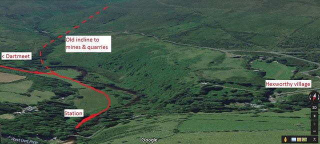
This is the setting of the station at Hexworthy, as seen by Google from the North West. The station lies along the river bank by the narrow stone bridge (bottom left), some way from the village of course! The mines and quarries are scattered along the top of the ridge to the South (right and top).

Now I plan to set my model in the present, or recent past, as a preserved line. This railway would have made a popular tourist line and although there would be no goods traffic, the works trains seen on preserved railways offer opportunities for interesting models and operation. I also like the juxtaposition of well-kept stations, locos, and coaches, with grotty maintenance wagons, workshops, stores, and even decaying stock awaiting restoration, that is often seen on "Heritage" lines. The fact that an imaginary preserved line is a great excuse to run whatever stock I please is a happy coincidence (honest...), but preservation is an era and setting that I, and many others who never knew the steam age, can relate to.


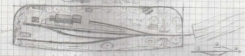
Plan1

The idea for this layout has formed over the last couple of years, with dozens of plans sketched, but this is the final design. Earlier variants tried packing more in - with a workshop or engine shed, but I settled on "less is more" as preserved or not, I want to capture the open remote feel of the location. As well as a run-round loop there is a bay platform for spare coaches or "special" trains, this is a truncation of the old goods siding as the goods shed will be the station cafe. Along the river bank the quarry exchange siding is now used for maintenance trains, with an old shipping container or similar used as a store. Of course there will be a car-park, and maybe a playground, but it will be a quiet sleepy place between trains.

IMG_1978

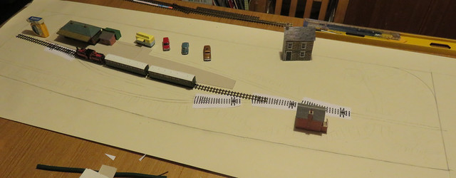
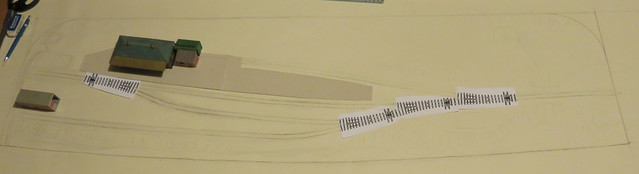
Sketches are useful but I always like to do a full-size plan before starting work. A roll of lining paper, some downloaded plans of PECO points, and a spare length of flexi-track are the essentials. A few buildings and vehicles are used to get scale - though any suitably sized object will do - and some stock placed to check clearances and perspective. It's very easy to rub out lines and move things about until things are just right - and on a small layout like this, half an inch either way can make a big difference to the way things look, and work!

IMG_2028

Saturday, 19 March 2016

Using Map Data

Recently a work discussion about getting map data - in that case the altitudes for a route - resulted in a colleague pointing me at this website:
https://www.daftlogic.com/sandbox-google-maps-find-altitude.htm
It didn't take me ling to think of non-work uses too. As a teenager I doodled many track plans, and often schemed out "might-have-been" railways on Ordnance Survey maps. I'd attempt to check contour lines crossed against distance to ensure they weren't implausibly steep, but it wasn't reliable and as I was often planning Narrow Gauge lines through hilly landscapes the gradients would have been pretty severe.

So I plotted one of my favourite schemes using the website, clicking points onto the map, the "Terrain" view gives contours which help. The string of co-ordinates produced can be copied from the box below the map which I pasted into a text file, then imported into Excel. Plotting the latitude and longitude and placing a map picture behind the plot is a quick way of drawing the route - the Excel plot can be stretched either way so I made sure the two end points were correctly positioned on the map, the rest will then be correct. Click the images to enlarge them.


That's rather fun but the data allows much more analysis - easy enough in excel, even if it is rather like the day-job! This site gives the formula for distance between co-ordinates, so of course gradient can be determined (change in height over distance). However for that I used an adjusted altitude - representing the track height after civil engineering - and calculated the deviation of that from the ground, i.e. the magnitude of the earth-works. The gradient can often be eased by increasing the height of embankments and cuttings, but for a Narrow Gauge line the balance would be in favour of less costly earth moving and more gradient. It's worth bearing in mind that a delta of a couple of meters can be regarded as negligible, and since my route is often running along the side of a slope, it only represents a few meters deviation of route - or of inaccuracy of my mouse-click on the map! I did go back and adjust some points to get a better route.

So here's my analysis. This line does have severe gradients - 1 in 44 for a sustained period, with another at 1 in 37 at it's worst - but these are not unusual for NG lines (the Welshpool and Llanfair has a section at 1 in 29) and are a good excuse for short trains! That does mean the earthworks are minimal, though an embankment or viaduct up to 25 ft (8m) tall is required to cross a valley just beyond Scorriton, and a 25 ft (8m) deep cutting is needed at Holne - both are plausible for this kind of line. A bridge across the West Dart is also needed near the end of the line, but at a point were that would be relatively easy.


This plot shows the altitude of the line (black) with the terrain (green), and also the gradient as a percentage (so 1% = 1 in 100, 3% = 1 in 33).


So I have a plausible route for an imaginary line, and I'll tell you about it's history another time!

Monday, 27 July 2015

A plan for two gauges

I've always enjoyed doodling track plans, I have a couple of box files of plans from my younger years. So many ideas, so little time to build them, but even so I still occasionally doodle plans for fun. Last week an unplanned and somewhat dull stay in hospital gave me the, er, opportunity to doodle...

Here's one of the ideas that emerged, and it features both standard and narrow gauge. I've long wanted to have both on the same layout but sadly didn't finish the last layout I tried this. This plan keeps the OO gauge to a minimum, just a simple inglenook shunting puzzle provides operational interest without even a need for a fiddle yard. The narrow gauge (009) has a low level continuous run for easy exhibiting, and also a small shunting yard, perhaps with workshop or engine shed, at an intermediate level by the SG siding. Sharp curves (about 8" radius) and gradients (about 1 in 30) allow the NG to emerge from bridges either end, pass along in front of the layout, and climb up to the level of the SG yard - the small numbers are heights in cm.


The overall size is 4'6" by 19" allowing it to be built as one board, though a larger board would help. The rear 6" provides hidden staging for the NG to swap trains, cassettes could provide more capacity but aren't really necessary. Actually the rear section could be made removable or fold-up to allow the scenic board to sit on a narrow shelf at home, the lack of continuous run and staging being less important than the display and shunting.

The big question is the theme and setting. Obviously an industrial scene, a quarry/mine, gas works, water works etc. are all possibilities, though need bulk transfer of coal or minerals which is tricky to model. I'm thinking a large factory with an internal system - such as a chemical works (I grew up near ICI plants with internal rail systems), or a paper works (like Sittingbourne), would work well. The NG would move loads around the plant as well as transferring goods to and from the SG, while SG wagons would have more variety and be loading/unloading direct to the factory buildings too. Another option would be a munitions factory or MoD site, perhaps a good excuse for the Narrow Planet RNAD loco and crew van, and the 009 Society wagons kits with some "interesting" loads...! These themes could work from the 1930's right through to the 1980's with appropriate stock.

Whatever the purpose of the site, scenically there is a lot of track (much of it a little overgrown perhaps), with grassy banks and undergrowth.  The left hand end would be built up to suggest factory buildings and warehouses - I'm thinking more modern brick and concrete Scalescenes type rather than the older and slightly twee Metcalf kits - while the right hand end looks more rural, the SG on an embankment surrounded by trees. A stream passing under the lines could add interest, with a rural backscene contrasting with the industrial foreground.

Well I don't know if I'll ever get to build this layout, but it would be a lot of fun in a small space, with up to three trains running at once.  It would also be a good layout to build with my son, to include standard "OO" trains along with the 009 I prefer. And I do have a Model Rail "OO" Sentinel shunter put aside...

Monday, 10 November 2014

Trainset Mk 2

A few years ago I built a train set for my son, which folded to go under his bed. We moved house last year and in the summer I redecorated his new bedroom, and we got him a new bed - which didn't allow for the storage of the layout. In any case he was growing out of the simple train set, and it had some limitations including an over-tight curve on the inner track, so I had promised him a bigger layout in his new room.

We'd arranged the room so one wall was mostly free, and I figured the best approach would be a board that folded up against the wall. I'd suggested this for my Nephew and the concept (as built by my sister-in-law) seems to work well. I worked out the space available was about 7' 6" long by 4' 6" wide, leaving space to access bed and wardrobes even when the layout was down - which should allow it to stay up overnight. It's also a reasonable size for a layout I thought, so I doodled a few plans which he looked at, thought about, then he gave me his brief:
  • A double track oval for running trains - and including his sister or friends
  • A high-level track, ideally with bridge
  • A big station with lots of platforms
  • Goods sidings
  • A second station
  • A turntable and engine shed
Phew, a demanding customer! Now the space doesn't seem so big. A few more sketches later I had an idea, so tome for a full-size plan to check. Lining paper was laid out and boxes of track dug out the garage:


It's ambitious but seems to work, so I got a couple of 8' x 4' sheets of 9mm Ply. I'd worked out the main board sizes I needed so I could get the timber merchants to cut it, which also meant I could get them in the car! The layout is made of 4 boards: 2 of 4' 7" by 2", one 3' 6" by 21" and one 3' 6" by 14", and all include some aspect of double-levels. Mostly cross-framing is using 2" x 1" timber but ply was used on the more complex sections, with smaller timber for screwed joints. Ply fascias on the outside are considered part of the framing, and the extra depth adds strength, while the double-deck section should add rigidity along the length of the board too.


This took me quite a while, which is when I realised I'd never built a layout this large or complex before! Anyway here are the four boards laid out together, the rising line and upper section are clear. The front and rear fascias have yet to be fitted, as they will be cut in two sections and bridge the gaps between the three boards, adding rigidity. Note that the front has developed a slightly curved frontage to push the middle board out, easing the curve on the rising line and maximising the access hole in the middle.


Tuesday, 16 April 2013

Hang on lads, I've had an idea...

I do like doodling track plans and layout ideas, I just can't help myself. Regular readers will know I have a weakness for "challenge" micro-layouts, such as the Dave Brewer challenge at EXPO-NG. This year's rules are for a triangular layout with sides in proportion 45:40:30 (up to 1.8 cm times those factors), now I have no intention of entering but still couldn't help sketching some ideas. Then I came up with this plan:

 
This is a full-size mock up for an 014 layout inspired by the Thakeham Tiles Railway, which was used to deliver sand from hoppers (previously a quarry) to the factory which made concrete products such as garden walling (confusingly, not tiles!). Thakeham Tiles are still trading from the site in Storrington, West Sussex - just a few miles from my home - but the railway ceased operation in 1982. Fortunately the locos were preserved at Amberley museum, and there is a book about this simple but fascinating line by Graham Lelliott.

 
The idea prompted me to dig out the book, which showed that a more accurate plan could in fact be fitted in to the area. I ditched the short siding in favour of one next to the engine-shed, where it actually was, meaning the loco always operates from the factory end of the train (2 skips), which it did. This even meant there was space to fit in the footpath passing under the line just before the factory tipping shed. Hopefully this is clear on the plan below - the sand hoppers on the right, shed at the bottom, and factory on the left.

 
The front cover photo of the book shows the train rounding the curve by the engine shed, just beyond the shed can be seen a spare skip wagon on the siding. The scene is dominated by the concrete walling products awaiting dispatch.

This would make a somewhat different model - not exactly interesting to operate, no an accurate rendition of the prototype, but close enough to capture the main features of the line. However there would be a lot of work - not least, making all those concrete blocks! And the competition is only 6 months away. So should I give it a go? Hmm....
Posted by Picasa

Sunday, 13 March 2011

A Brief History of Landswood Park Farm

Landswood Park was one of the large estates of Cheshire. Home of the Marshall family for several generations, the Hall dates from the 18th century, and makes a grand impression as approached from the surrounding parkland. About half a mile to the South of the Hall lies the Home Farm, one of several farms owned by the estate and closest to the Hall, but Home Farm (also known as Landswood Park Farm) was managed directly rather than being let to tenants. It was predominantly a livestock farm, with pigs, cows (mostly dairy), and chickens, however it also grew vegetables such as potatoes in fair quantities.

At some point in the 19th century a hand-worked rail system had been installed in the farmyard for making the job of carting animal feed around the cobbled yard easier, this was considered the height of technology for farmyards at the time! However some of the farmworkers returned from the Great War having seen what railways could do over muddy ground, and wondered if the same technology could be of use in their farm.

So the farm manager, Edmund Blackadder (who had reached the rank of Captain on the Western Front) put a proposal to Sir George Marshall, the lord of the manor at that time, who happened to be keen on modern developments, and permission was granted to purchase second-hand 2' gauge track and stock from the war department, including a petrol locomotive. The farm workers laid the track and it was operational by the winter of 1920.

Initially the line served the Landswood Park Farm yard with lines into some of the surrounding fields, however by 1922 it had been extended as far as the yard of the nearest Cheshire Lines Committee station, a distance of around 3 miles entirely over Marshall land, other than a road crossing by arrangement with the council. By 1927 it had reached it's full extent, with around 6-7 route miles of permanent track, serving two other farms on the estate, a wood yard in the forest, and a branch to the service yard of the big house to bring in coal and other goods from the station. Temporary tracks were laid into the fields for harvesting the vegetables.

Traffic included animal feed from the station to the farm stores, then to the various barns and fields, plus of course mucking out of barns and stables - the contents went to the potato fields. Bagged fertiliser and seeds were also transported. Coal was taken from the station to the Hall, the farm dairy, and for traction engine and domestic use across the estate. Out-bound traffic included potato and other vegetable crops, and timber. Occasionally even livestock (piglets and chickens) were transported, and in later years a pair of wagons were modified to carry fuel for the growing fleet of tractors and lorries. Some wagons were converted to carry passengers, probably labourers for the fields at harvest, but this was of course unofficial!

The initial purchase of stock was soon inadequate and worn out. Generally the estate bought off-the-shelf items from Robert Hudson of Leeds, including track parts and wagons, note that 4-wheel wagons seem to have been preferred - possibly due to the tight curves and uneven, lightweight track. Records of the locos used are patchy, and as Sir George and his Farm Manager were canny at persuading potential suppliers to loan locos for trial periods, photographic evidence is confusing. It seems that there were up to 3 or 4 locos at one time, possibly not all in use at once, but we do know that a Lister RT Railtruck was popular for use around the farms due to it's light weight. Trains were generally short as the loco's struggled for traction in places (the track tended to follow the lie of the land!), so the in-service loco spent all day pottering around the estate.

By the mid 1930's the estate was experimenting with tractors and road lorries, and domestic traffic became rare on the line. However WWII and the demand for farm produce kept the line busy, and even as tractors were introduced they didn't replace the railway. Since most goods at that time came via the station the railway was still economic. By the 1950's though most goods were being sent by road lorry, the railway line was worn out and deemed uneconomic because of double-handling, it is believed that it last operated in 1960.

Wednesday, 2 February 2011

The Boxfile Plan

The idea of building a layout in a box file is not new, I remember reading about an 009 layout in two joined box files in a magazine back in the 90's, and it was probably not the first, although micro-layouts seemed less popular back then. Phil Parker pointed out the Double-O Gauge Association ran a boxfile competition a few years back, and I should say I really admire Phil's own Melbridge Box Co.

Designing a successful micro-layout is not easy, particularly with such tight constraints. Of course "trains" must be short, curves and points tight, and operation will be limited. However while the layout may be a gimmick (let's face it, it is), I want the model to be serious - that is I want (reasonably) interesting operation that is not un-prototypical, a setting that is plausible and not too contrived, and of course to build it to the best standards I can manage. Even with some experience of such small layouts that is a tall order!

The size of the box file and the rules are not the only constraints to the layout design. While the Hudson "Type 1" curves are very tight (93mm radius), allowing for very short points even in 7mm scale, they are not ideal for shunting over and limit stock to the shortest possible, so "Type 2" (260mm radius) are preferred. Experience has taught me to allow enough straight in sidings where coupling and uncoupling is to happen! And while the lead track or "cassette" can be fixed to multiple openings in one end of the box according to the rules, I don't find moving a cassette "interesting" operation, so prefer that to be used only for changing stock

Most industrial 2' gauge lines were built for one traffic, e.g. quarried sand or aggregate, so operation is not always interesting. Also while NG may be ideal for a cramped site, many industrial sites and quarries sprawled over large areas. So what prototype could provide a plausible and interesting setting? Well, regular readers may remember my post about Narrow Gauge in a Farmyard - nearly 3 years ago I found this hand-worked line at Tatton Park Farm in Cheshire, and postulated that it would make an interesting layout assuming locos were used!


The plan I settled on is essentially an Inglenook (3 sidings that can form a shunting puzzle) with the addition of a kick-back. This is the same as I suggested to Phil for his Melbridge Parva layout, and indeed used for my own Pen-Y-Bryn Quarry, as it is a versatile plan for a small space. Here the line enters under an archway (similar to Tatton but much smaller) and splits into sidings serving different parts of the farmyard: a feed store, livestock shed, stables, and a heap of coal (for the dairy as well as domestic use). The kick-back is the blacksmiths, also used to stable and repair the loco(s).


The next task was to mock up the buildings - cereal packets were cut up and stapled to approximate shapes. Being new to 7mm scale I needed to visualise how big the buildings would be, and check clearances. You can see I changed the design of the buildings along the rear slightly, but all seemed to work. Of course the upper parts of the buildings will need to be removable to allow the lid to close.


Posted by Picasa

Monday, 9 November 2009

Some Track Plans for Phil

Over on his Blog Phil Parker is planning a new micro layout in a space 73 x 20 cm, or about 2' 5" by 8". Now that's not a lot of space in OO, however I like a challenge and I just can't help doodling track plans, so for Phil here are some ideas!

Like Phil I prefer sketching out plans, as somehow track plans are very "organic", so I have simply inked over my sketches and scanned them in. I use squared paper and in this case 3cm to 1 foot, or 2" to each square. I've allowed for point lengths and clearances but these plans are just approximate, for any micro layout a full-size plan would be a great idea, using the Peco point templates (send them an SAE!) and actual stock to check clearances. You can even use boxes and card cut-outs to check buildings fit and appearance.

Phil mentioned an Inglenook, which is a minimal shunting plan with 3 sidings, and often used as a puzzle. However to fit this plan I've used the reduced size with sidings for 2-2-and-3 wagons, and a headshunt for a loco+2 wagons. Even then I've suggested wye points to save space! I've sketched an industrial scene, the gate to the front left might lead across a road to the main railway yards. This system might be operated by small industrial locos, and for interest there is a small engine shed, although operationally it does not really feature.

The next plan features a full-size inglenook, for 3, 3, and 5 wagons. However to achieve this an external fiddle yard is required, but that would rather defeat the point of building the layout in the box Phil has! So my idea is to hinge the yard such that it folds over the layout, when open a bridge could easily hide the hinge pillars. Using cassettes would allow the fiddle yard framing to be on top of the deck, saving height when folded into the box.

I've added a kick-back siding again but this time run it under the bridge to suggest the end of a run-round loop, adding a little operational interest. Indeed a small platform could be squeezed in, OK a station is unlikely but perhaps an internal system running works passenger trains would be plausible, maybe a naval base?

Another good basis for a micro layout is a locomotive depot, after all you're never going to run much in the way of a train in 73cm but if you like locos (and who doesn't?) this gives a great excuse to show off your collection without bothering with stock! This plan is a rather small depot, and like my Southon Yard 009 loco depot only the front of the shed is depicted (we want to park the locos on show!). I've used a coaling stage to hide the exit track, but if that seems a bit grand a works building of some kind would do - a wagon repair shop if you like wagons.

However despite using a 3-way point, to allow reasonable space for locos on display there isn't really space for a fiddle yard, even though all that is required is a cassette for a loco. In fact the Peco Loco Lift would work a treat, even if just the end rests on the lead track. To support the other end of the cassette or loco lift perhaps the end of the baseboard could incorporate a telescopic or hinged arm!

The final plan takes on another aspect altogether. Phil wants somewhere to pose locos and stock for photographs, which brought to mind those ex-works photographs seen in books where the new loco is posed on the works traverser ... hmm, how about a model works traverser! This plan is completely pointless (!) and features the traverser at the centre. Making it work could be a challenge! To the left are sidings to pose locos and stock outside the repair shops, for added interest the back siding could be the goods inwards loading dock. For a fiddle yard the same cassette system as the last plan is used, hidden by the erecting shop and a raised walkway.
Posted by Picasa