Showing posts with label uncoupling magnets. Show all posts

Wednesday, 22 April 2026

Hexworthy preparation for Narrow Gauge South

Hexworthy will be at Narrow Gauge South at Eastleigh on Saturday, so I have been carrying out the usual preparations (a quick vacuum) and testing (running all the train combinations I can think of). There were a few minor jobs to do too, including looking at the exhibition fiddle yard following some occasional issues at it's last outing at Chatham last year. 

The probable cause of the occasional derailment or unwanted uncoupling was mismatched rails between the lead track and the traverser.  A couple of rails needed lateral adjustment, but several had a slight change in height. The rails are soldered to PCB strip either side of the join, so adjustment meant applying a soldering iron until the solder melts and holding the rail in the right place (including up slightly where needed) with pliers while it cools. All seems good now, hopefully it will stay that way!

The deck had become stiff to turn, and had started squeaking when turned. The pivot is simply a bolt which had a washer, nut, and locking nut underneath - the lock nut preventing the nut coming undone. When I looked underneath I found the nut had wound itself tighter upward into the wood support, forcing the washer with it - while the locking nut stayed where it was. Here, I've removed the lock nut and the normal nut is about to be removed, but the washer remains embedded about 2-3mm into the timber.


The solution was a bigger washer, and using just the lock nut which shouldn't loosen or tighten. The tightness has been adjusted so the deck spins freely but there's no vertical movement. The old washer remains embedded in the wood - I guess it can act as a bearing!


The end gates for the deck folded down to rest on the rails. The problem is when the deck is slid back and turned, they could catch on the fixed tracks, and the resulting jolt derails most of the stock on the deck unless it is turned very slowly and carefully! The solution is simply a screw (seen centre) acting as a lower stop, holding the gate high enough to clear obstructions when turning. 

I also made an adjustment to the latching arm release mechanism underneath. This pushes the sprung notched aluminium arms (seen lower left in the photo) away from the alignment pegs so the deck can traverse smoothly. I took a photo, but it doesn't really help explain things unless you know what your looking at - so suffice to say the lever doesn't need to be pressed so far to allow smooth deck movement. 


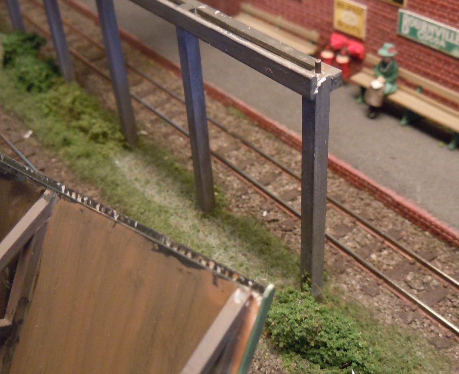
My operating team say that the birds on the canopy are not sufficient to accurately position the train for uncoupling. Something to do with the operating position being four feet away to the end of the layout. In an attempt to make uncoupling easier, I've added tufts of grass. The idea is that with the overscale blue tit in line with the coach roof and the grass by the end of the footboard, together being easier to judge from an acute angle, the coupling should be over the magnet.


The other tuft of grass of course aligns with the robin, the marker for the Microtrains uncoupler magnet. In both cases the trick is to stop beyond the magnet, then set back to the markers to uncouple. We shall see how much the grass tufts help...

Now I just need to pack up for the show. It looks well worth attending if you can - do say hello. 

Wednesday, 30 October 2024

Fettling Hexworthy between shows

On Saturday I'll be taking Hexworthy to the Newhaven club exhibition (in Seaford). Following the two days at Uckfield there were a few issues I wanted to address to improve running. One was the uncoupling magnet under the bay platform line - this seemed to "grab" at metal wheels of coaches causing jerky running, and the small quarry Hunslets could actually stall. Operationally, the magnet isn't needed as I don't use the bay as a siding, stock remains coupled to the loco, so the obvious solution was to remove the magnet.


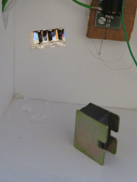
The cupboard-catch magnet had been stuck in place through a hole in the foamcore board using hot glue, such that it sits just below the sleepers. Cutting the glue away allowed the magnet to be prised away, but of course this brought some of the ballast with it. 


Fortunately, the little oblongs of ballast were so well set in glue that I could slice them off the magnet intact with a scalpel. Having stuck a piece of card under the sleepers, the ballast blocks could be glued back in place!

There had been occasional derailments exiting the fiddle yard, I think due to misalignment of the traverser. The traverser/turntable deck has a "lip" which passes under the fixed edge to prevent the deck rising up, but I think the fixed deck might have been rising slightly. 


I've added a lower support, the wooden "finger" seen horizontally protruding from the fixed deck under the traversing/turning deck lip. Hopefully this will constrain any vertical movement. I also filed the vee notch in the aluminium arm a little deeper and more symmetrical, and increased the spring tension. Originally I'd been aiming for smooth movement without having to disengage the latch manually, but that wasn't really possible, so now the latch can be disengaged via a single lever I could have a more positive alignment via the deeper V and stronger springing. 

Up top, the alignment of rails was checked, a couple of tracks were adjusted slightly with the soldering iron. A couple of rails were also trimmed back a fraction of a mm, although they cleared the entry tracks fine one of them caught on them at Uckfield, I can only presume due to heat expansion or distortion of the frame. I've also added a switch to isolate the traverser tracks, regardless of position. To access the bay locos draw their coaches back into the fiddle yard, this can happen when all tracks are in use which could be done by moving the traverser to a "between tracks" position so no track was live, but the addition of the switch makes this easier. 

A quick test suggests coaches can be pulled and propelled on and off the traverser, but they could most of the time before, so we'll see if things are more reliable. The latching feels more positive. If you are at the show on Saturday you can see for  yourself - do say hello!

Friday, 14 October 2022

Magnet markers

This week I've been preparing Loctern Quay for its outing at Uckfield model railway exhibition this weekend. Being a small layout this isn't especially onerous task, and thanks to the use of graphite I don't need to clean track or wheels, though the graphite is topped up in a few places. However the layout does get a vacuum and dusting with brushes, and a thorough test. All locos are tested including couplings against one wagon, and all wagon couplings are tested against one loco. A few couplings were adjusted, and one wagon which was reluctant to uncouple got a small block of foam positioned to rub against a flange. 

A couple of detail junk items have also put in an appearance. My assistant operators sometimes struggle to locate the magnets, now those on the front sidings are in plain sight but they do disappear when a train is over them, particularly the front siding, and the rear siding magnet is invisible under the track, so they do have a point. I figured a discrete marker by each magnet might help.

The chain I've had in the bits box for decades, I think it must be iron since it is attracted to magnets but it is plated in some shiny bronze-like material that resists paint. I tried applying gun-blue which had little effect but perhaps dulled it a little, so I dropped a length of it into gun-blue solution and left it for a couple of hours. As you can see, that actually worked. 

A length was then cut, roughly shaped, and dabbed with a little matt Modge Podge to see if that got it to hold its shape. That seemed to work, which allowed me to wash over some dark brown, then dry brush a little rust colour, followed by a dusting of weathering powder. The suitably grubby chain was then stuck in place alongside the front siding magnet with a little more matt Modge Podge. It's the first time I've used matt Modge Podge but I've heard it is a good scenic glue, drying without trace, and it seemed to work here.

The rear siding magnet got a couple of old sleepers. These are cut from Peco "crazy-track" with the webbing removed, the sides and ends roughened with a razor saw blade dragged across and rough emery paper, and the hole under the rail fixing filled with filler. They were painted dark "track" brown with the fixings picked out in rust, dry-brushed with pale grey, and then dusted with weathering powder. Matt Modge Podge was used to stick them down too, with a heavy weight to sink them into the grass. 

We'll find out this weekend if the markers help locate the magnets reliably, but hopefully they also add a little visual interest without looking out of place and being discrete as to their true purpose. If you make it to Uckfield - and I hear it will be a great show - do say hello, I'll be upstairs. 

Saturday, 20 February 2021

Magnetic uncoupling with standard 009 couplings

While I am happy with using Microtrains couplings for most of my 009 stock with its advantages in shunting, I have realised that fitting them to my Heljan Manning Wardle is too difficult but also unnecessary. It will only be likely to run with suitable coaches such as the Peco ones, and so long as it can couple up reliably and uncouple to run round the type of coupling doesn't really matter. So retaining the "standard" 009 coupling is easiest, except that the ones factory-fitted to the loco sit too high, and I've been unable to adjust them until they couple reliably to the Peco coaches. 


A while back I bought a pack of Greenwich couplings to fit the NEM socket, these were bent up following the instructions and simply push into the sockets on the loco in place of the existing Peco type couplings. Being thin metal they are easily adjusted to sit level, which the Peco ones don't. As you can see here by leaving the loops off and the pivot tabs up (or cut off) they clear the cowcatcher easily. 


Being pre-blackened the Greenwich couplings look discrete but are entirely compatible with the Peco coupling - though since I have left the loops off the loco (to keep the cowcatchers) the coaches will need loops at both ends. I do need to provide some auto-uncoupling though, and I don't like pop-up ramps for the Peco loops.


So here is an ordinary staple held centrally in some pliers. Both sides were bent upwards from the flat plane of the staple.


This makes a U shape with the ends bent up - these tails were leaned back slightly, and trimmed about 3mm. 


The bent U shape is fitted over the outside of the Peco loop droppers. They can be tweaked to be a cosy fit, but not too tight as that can stop the loop moving freely. The upright tails are fixed with a little bead of superglue gel. The couplings are easily pulled out their sockets to have the staple fitted. 


The Peco coupling works normally, but when positioned over a magnet the staple pulls down which lifts the loop. If there are two loops a pair of magnets might be needed, but I only want to uncouple the loco (without loops) from the coaches so this should work well with one magnet. Here a tiny 2mm x 2mm neodymium magnet is held between the sleepers with blue-tack, a Greenwich magnet would be ideal but I don't have one, I will try a slightly longer magnet set under the sleepers which should work with less accurate positioning. However, the experiment shows this is a simple mod to add magnetic uncoupling capability to the standard Peco 009 coupling. It might work with other types so long as the loop is not magnetic (the Peco loop is plastic).  The coupling on the Manning Wardle is level here and couples to the Peco coach, but does still look slightly high in this photo, a quick adjustment with pliers should fix that. 


Friday, 4 October 2019

Adding magnetism

Being designed for shunting, the challenge layout needs uncoupling magnets. This was taken into account when designing the track plan; the sidings are straight with space for the magnet at the entry. I've used the Microtrains magnets, which sit above the baseboard between the rails - visible, but not overly obvious. However they are rather long; I have found the can be split in half by clamping in a vice and giving it a sharp well-placed tap, resulting in two magnets of a more manageable size.


Below you can see three magnets placed to allow "inglenook" shunting. The problem is uncoupling the incoming train - the rear track is long enough for the wagons but not long enough for them to be pushed past a magnet to allow them to be re-coupled! So another solution was devised, which sits below the yellow-brown paper seen top-right.


OK it looks a bit Heath-Robinson! The magnet is on the left, next to the point motor, it is taken from a cupboard catch, and sits in a hole in the baseboard so it is just below sleeper level protected by the paper layer. The magnet sits in a frame made simply from plasticard. You can also see a dowel and a piece of wire (paperclip!) linking it to the magnet-holding frame, which should become clearer in the next photo.


Here the magnet can be seen swung away from the baseboard. The plastic frame that holds it is pivoted around a simple bolt from a bracket glued to the baseboard. The wire links the pivoted frame to the dowel, the linear movement of which swings the frame up and down. The two screws in the dowel act as end-stops against the block of wood.


The dowel runs right along the baseboard to the far end, set low enough to clear all the other under-baseboard mechanisms and wiring. It is now surprisingly busy under here!


At the end the dowel protrudes just enough to be pulled - pulling on the dowel raises the magnet to the track, pushing it back in lowers the magnet. The dowel is close to but just around the corner of the baseboard from the control panel for convenient operation at this end of the layout.


It seems to work well in testing despite the basic construction methods, and should allow an incoming train to be uncoupled, without preventing an outgoing train from coupling up. I guess the same approach would work with a servo, or possibly a slow-action point motor, allowing retractable magnets to be used on a larger layout.

Wednesday, 18 October 2017

Fitting Magnets

Before going much further I needed to fit uncoupling magnets. I find the Microtrains surface mounted magnets work well, but are too long, so I snap them in half before fitting them. They stick up between the sleepers so while they can be disguised as board crossings, it is nice to have hidden magnets in some places.

In the past I've had some success using cupboard latch magnets set below the sleepers, though on Awngate they needed strengthening with neodymium magnets attached to them - I think the plywood baseboard diminished their power too much? Heworthy has a foamcore base so I think they should work well.

IMG_3898

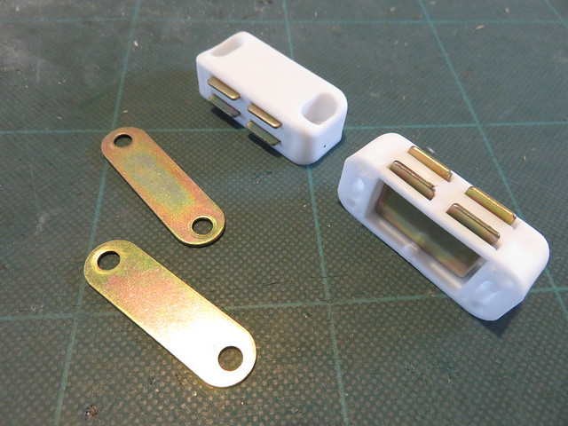
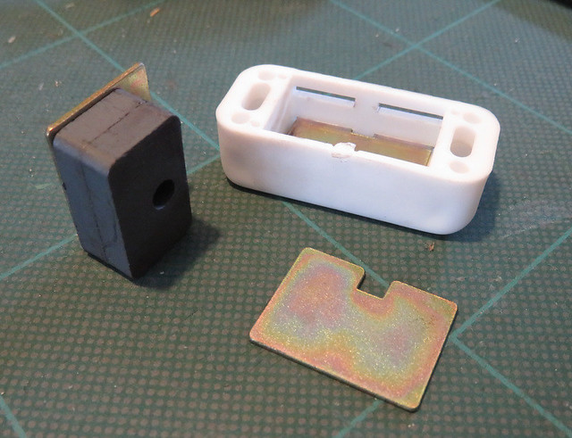
The staring point - a pair of B&Q magnets. Bought in packs of 10 they work out quite cheap.

IMG_3899

The magnets are popped out with a screwdriver and snapped together, the magnetic field is between the large faces, and two together is wide enough where one would not be. This time I attached the steel plates to the outside as I think this will "focus" the magnetic field at the poles in the same way they do in the cupboard latch, or a steel pin does through an electromagnet.

IMG_3900

The completed magnet assembly, and an oblong hole cut through the baseboard under the track. The foam core is at least easy to do this with a sharp scalpel - with plywood the hole would have to be cut first.

IMG_3902

From above, the cupboard catch magnet is rear right, under the sleepers, the Microtrains surface mount (cut in half) is front left. At this stage the cupboard magnet seems much more powerful than the Microtrains one, but ballasting may change that.

Now I shall have to do some testing to check they work well, and that I have them in the right places.

Tuesday, 11 February 2014

Fixing and Fettling

I've always been frustrated with the poor running of the Skylark I built a year or so back. The Kato chassis just didn't seem to perform as well as other people's, and indeed the one I have under the railcar, it would run smoothly at speed but stall frequently at lower speed. I'd checked the wheels were clean and all appeared to be in order, but running didn't improve. It would be nice to have it running well for the Shepton Mallet show next week, so last week I took the loco along to a Sussex Downs group club-night and with the help of others we set about a diagnosis.

Eventually, as suspected, we traced the problem to the pick-ups. Although they looked fine, they clearly weren't making good contact, there may have only been one working pick-up each side. We found the only way to fix this was to remove the white clips on the top of the chassis (carefully, they can ping!), and ease up the pick-ups where shown with the yellow arrows. We did one end at a time, and as well as cleaning the pick-ups I tweaked their shape to have more of an outward splay, before feeding them back in behind the wheels. While the chassis was apart we applied a tiny drop of oil to each worm too. 


The result is a chassis that runs as smoothly as it should, without stalling and controllable down to a slow speed. Since I was rather pleased with the way the body came out, it is great to finally have the loco running as well as it looks!

Spurred on with that success, I thought I'd address the uncoupling magnets. The Neodymium magnets I had tried in two locations really hadn't worked, they are actually too strong - wagon wheels and coupling tails shoot towards them, sometimes resulting in derailments. However in trying to excavate them I managed to damage the track - it didn't help that there are double rail-gaps and cut-about sleepers over the hole in the board for the magnets, but having rails sticking in the air was never going to work! And with a week to go before an exhibition this is not ideal.

Fortunately I managed to bend the rails back flat (it was the fishplates that had bent) and added a new "spare" Peco sleeper. A piece of paper was glued in place under the track (to support ballast), then the original cupboard-catch magnets inserted from below with lots of hot-glue to hold it. The glue-gun was also used to stick the tips of the sleeper to the baseboard. By this point the track looked like it would at least support trains!


I dug out some fine ballast and tapped it into place between the sleepers, not too thick to not limit the magnetism, but enough to cover the paper and glue lumps! Finally a little acrylic paint was mixed up and slopped over the lot to blend it in. The colour may not be an exact match, but I've tried not to be too even anyway so it looks fine.


Phew, disaster averted. Back to cleaning wheels and testing stock...!

Thursday, 12 April 2012

Preparing for Narrow Gauge South

With Awngate being exhibited at Narrow Gauge South at Winchester this coming weekend, things have been getting a but frantic. I've got this week off work, the idea was to have some family days out, but between the rain showers and my daughter having chicken pox, outings have been somewhat limited. This has meant I've caught up on the progress I had hoped to make by now.

 
One job I have been meaning to do for a while is to try and get the station roof to sit correct, as it has a habit of pinging off the support legs which lean inward too far, making the roof sit too high. It may not be obvious, but it looks wrong to me. The solution was to drill a hole in the top of the support post and insert a piece of stiff wire (paper-clip), as shown above. Not so obvious is that the roof (upturned in the foreground) has a similar hole for it to locate in. This is just enough to hold the roof and support together securely, as shown below.

 
The engine shed has been painted and detailed, at least as much as I can for now, but more on that another day. While bedding it into the scenery I tried out a new toy - this static grass applicator bought off ebay for £10. All right, it is just an electric fly-swat mated with a tea strainer, but for that price it was worth a try, and first impressions are that it works well. Now a £100 branded device might be better, I don't know, but it is a lot better than the puffer bottle and a fraction of the price of the brands...

 
Further to the experiment with magnets in the last post, I have fitted the ends of the train cassettes with pairs of magnets beside the track. The idea is that as the loco stops on the non-powered loco cassette, the magnet uncouples it from the train. Some manual shuffling may be required but it should be much easier to separate the loco than before. As the magnets are at the rear of an outgoing train there should not be unwanted uncoupling.


I have also been cleaning wheels and testing locos, as well as checking everything is ready. I must find the drape to hide the trestles ... anyway, still lots to do. However if you can make it to NG-South this weekend (it promises to be an excellent show as always) do come and say hi!
Posted by Picasa

Monday, 9 April 2012

A tale of two magnets

You might remember a little while ago I bought some magnets:


The idea was to use them to replace some of the cupboard catch magnets under the track on Awngate, as some were not working very effectively. To space them sufficiently far apart I used a steel nut that happened to be a suitable size.

 The magnets were then affixed under the track in the existing hole, having removed the old magnet. The picture below shows the new magnets and nut (right, the blu-tack was holding it while the glue set), with an old pair of cupboard-catch magnets (left). The difference in size is apparent!

 
Sadly this didn't work as well as hoped, although the couplings swung over there wasn't enough pull to separate them when coupled. Also it had proved tricky to centre the magnet under the track. However my experiments on the workbench had shown good results with the magnets to the sides of the rail, so I cut away the ballast and the ends of one sleeper outside the rails just enough to slide a magnet in. This went down to the baseboard, as the track is laid on 1/16-inch cork the magnets on edge sat level with the foot of the rail.

The picture below shows how unobtrusive this is - the front and middle tracks have had the new magnets fitted - again one has blu-tack to hold it as I made the hole too big. This proved to be much more effective than mounting them under the track. They have since had a few grains of ballast on top and to fill any gaps, and have been painted to match, blending them in nicely.

If these work better in-use than the other cupboard catch magnets I might replace some more, it wasn't too hard to do. In any case, it's useful to know for future reference, as no baseboard holes are required.
Posted by Picasa

Monday, 13 February 2012

More Magnets

I recently bought these over the internet:


No, not gold bullion, but neodymium magnets! These are just 10mm x 3.5mm x 2.5mm, so quite small. However they are incredibly strong - it takes a lot of force to separate them from this cluster. The poles are on the largest faces, conveniently, as you have probably guessed I plan to use them in pairs for uncoupling.

A quick test on the workbench (below) suggest they will be plenty strong enough for this, even when placed outside the rails. In fact I plan on replacing some of the cupboard-catch magnets on Awngate with these placed under the track from below, probably under the rails, spaced apart with steel washers. Experimentation to follow!


Posted by Picasa

Sunday, 7 August 2011

Adding the "Stick"

The rules of the challenge allow a single cassette, described as a "Stick, to be attached to one end of the boxfile as a fiddle yard or headshunt, it can also be attached to multiple opeinings. Clearly my plan for Landswood required such a "stick" to make it runnable. I wanted to make a cassette that could be fitted to either of the tracks that leave the boxfile (although I doubt it will need to be connected to the shed/workshop line very often), and can be reversed - in order to allow wagons to be shunted to the workshop siding.


I made the cassette from plasticard, I could of use the trunking I used for Awngate but I didn't have any handy, and I only need a foot! To attach the cassette to the layout I used brass rod in brass tube. The rod is soldered into the tube on the cassette end, as it couldn't sick out of the boxfile! The cassette can slot into the layout with the brass tubes providing alignment and electrical conductivity in one easy move.


Now I can see you thinking, what stops the train falling out the end of the casstte? (If you weren't, I beat you to it!). So I added the gates in the picture below from L-section plastic, pivoted on a paperclip! They simply push up and down.


On the layout itself I have added uncoupling magnets. These are the Microtrains magnets, however as bought they are about 2" long, much longer than needed. So I break them in half to get twice as many for the money! I've also packed out the area surrounding the tracks with thick card.

Posted by Picasa