Showing posts with label baseboard. Show all posts

Tuesday, 22 September 2026

Shades of grey

I thought I'd better paint the boards before progressing further. It would be easier before there is (more) track and scenery added, and as it's best done outside, before the weather turns!


Loctern and Hexworthy were painted with a grey primer from Wilkinsons that proved to have a suitably dark shade and nice finish. However, that was oil based meaning it took ages to dry and brushes were a paint to wash - anyway, Wilkos is long gone. I got a water-based grey primer from B&Q which allowed me to get a couple of coats on and the boards back indoors before the moody skies looked too serious. 


Sadly, this paint turned out to be paler than expected, and much lighter than the grey I previously used - as compared below. The aim is for a neutral grey which won't distract from the scene, and I wasn't convinced the light grey would do that. It also had a chalky finish, I mean it is meant to be an undercoat, but clearly I would need a top coat.


So back to B&Q and I picked up "Princeton", a dark grey that proved to be a close match to the other layouts. It's also water-based so dried quickly, and being quite gloopy care was needed to avoid runs - there are a few, but not in obvious places. Note the card used to protect the existing scenery.


With the paint dry the latches and sockets were refitted and the pelmet and fiddle yard reassembled. It looks a lot more presentable on the outside now.


Friday, 4 September 2026

Whittlingly fiddle-yard baseboard

The next job was to add a short baseboard for a fiddle yard. In this case, the fiddle yard will have two entry tracks as it completes the run-round loop, but doesn't need to be long as trains will be a couple of 6-wheel coaches or 3-4 wagons and a tank loco. 

I didn't take many construction photos, but the sides and top were marked out and cut from the same 5mm ply as the main board, and cross-beams cut from timber. Before assembly, I remembered to set up the alignment to the main board, which used a couple of "bullet" type dowels - I had these and the catches in stock left over from a batch I bought for Hexworthy. It is easiest to clamp the ends together, then drill pilot holes through both from the back of one end - hence doing this before assembling the board. The holes were then drilled out to 7.5mm and the bullet and corresponding socket were tapped into place. 


The board is approximately 2' long by 1' wide and simply consists of a cross-beam at each end and one in the middle, with ply providing longitudinal support front and rear, and finishing off the ends.


Up top, the ends are profiled to support a shelf - on Hexworthy a shelf has proved useful for spare stock and tools. The rear panel has a cut-out to clear the turntable, and the deck has some cut-outs - hopefully, the reason for these will become clear later.


The upper deck curve was marked out with a "compass" made from a stick with a screw for a pivot and a hole for a pencil, it's 21" long. To get the deck height correct, the fixed part has 3 layers of 5mm ply (lower deck, spacer, top deck) - it seems that 44mm timber + (3x5mm) = 58mm, the 5mm ply is actually about 4.7mm! The turn-table deck sits on spacers of thinner (4mm ish) ply so it is slightly lower, this is for a cunning plan (we will see). I then marked out lines perpendicular to the curve for the track centres - there will be three tracks, but the outer two will be quite tightly curved. 


The turntable was then strengthened with some small strip wood and fixed with a 6mm bolt, a block of wood under the deck provides support to the pivot and depth to hold the bolt vertical. A strip of ply provides a lip and neatens the front of the shelf too. So far, it's looking pretty neat. 

Finally, the over-centre catches were added to hold the boards together. This was tricky as the 44x19mm timber forming the ends of the boards already has screws into it from the front and rear and deck ply panels, leaving little space for the screws holding the catch!


While it looks a small, simple board, getting the levels right while thinking about how the turntable needs to work made it quite a head-scratcher to make. I've come to the conclusion that "fiddle yards" are so-called because they are fiddly to make - or is that just me?

Friday, 14 August 2026

Growing Whittingly

Extending an existing layout that wasn't designed to be extended isn't easy, especially when it is a portable layout and it is fully scenic. So, I have been thinking about how best to do this for some time, but eventually it is time to take the plunge. It starts with removal of the existing low-height backscene. While this was screwed in place from the rear, the scenery had stuck to the backscene in places, and with trees and structures in the way it needed careful separation. 


The new 5mm ply backscene is longer, higher, and intended to be semi-structural in keeping the extended layout straight. That means it drops down to meet the cross-members of the extension, but, it had to sit onto the original board as the original backscene had. 


The new cross-member was attached to the end of the layout to support the deck extension, but being 44x12mm and the deck being 5mm ply, but the existing board being 55mm deep, a spacer was needed. Strips of the old 6mm MDF backscene were perfect, hence the blue. I also remembered to drill holes through the ends for wiring to be extended. 

The extension deck was then fitted with the outer cross-member from 44x24mm timber and another strip of MDF. The cross-members are also screwed to the backscene, and later, to the fascia, keeping the extension rigid. A similar process was followed for the right-hand end. 


Like the backscene board, the front facia is used to keep the board straight, and is cut from 5mm ply but with the top edge profiled to the shape of the scenery. I also cut an opening for a control panel, which was difficult to find space for without the extension. A second piece of ply was cut with a slightly smaller hole to fit behind the opening, this provides something to mount the recessed panel to as well as strengthening the fascia around the opening once glued in place.


A detail shot of the right-hand end shows the control panel opening in the fascia, the end panel fitted with 12x12mm strip wood to join in to the backscene, bracing around the top of the backscene board and end board, and the opening for the tracks. 


A view from the underside shows how the extensions have been added to the original board, and how the fascia (right) joins all together with spacer blocks to the original board's front piece (which is recessed). You can also see the cut-outs for magnets to be fitted below the track. 


The lighting pelmet is simply two pieces of ply at right angles, with timber bracing and strips at the end. The ends sit on the end board top-edge brace, which holds the end board, backscene board, and front "wing" piece together. A small piece of wood attached to this provides a mount for the lighting pelmet, with a captive nut a finger-tight bolt at each end is all that's needed to hold it in place. 


Note there are two bolt holes, allowing the pelmet to be fixed overhanging the front of the layout by a couple of inches to improve lighting at the front of the layout. Alternatively, it can be fixed further in to save width. 


So the small diorama now sits within a larger, "cameo" style baseboard. With an extra 6" at the left end and 8" at the right (the extra makes space for the control panel) it has grown from 2' 6" to about 3' 8" long - almost 50% bigger!


Next, I need to build a fiddle yard. And work out how I will add a backscene. 

Monday, 19 May 2025

Rail 200 challenge - getting started

With the plan decided, final adjustments to the positioning of the points was made - with a layout this size a few mm either way can make a difference to how the layout works.


The straight track here is offcuts of code 100, I've yet to cut any track. The medium radius point on the front track was in stock from a previous aborted project, I could use a small radius here but medium matches the 3-way and fits. It won't be fitted until after the challenge anyway. 


Track positions and key marks such as holes for point tie bar operation were pencilled onto the board. I've also thought about anywhere I might want an uncoupling magnet - I'm not sure what couplings I'll use yet, not having used OO for a long time, but the previous aborted project had used Kadees so they are most likely. I need to look into NEM fitting Kadees for more recent acquisitions though. 


I then drilled the holes and used the jigsaw to cut out openings at the possible magnet locations. Magnets won't be used at all of these - it will depend what couplings are used and where works best - but easier to cut openings now! 

I found a strip of 6mm MDF about 160mm wide and long enough to form a backscene along the rear and both ends. The height limit for the challenge is 140mm above the baseboard surface, so I cut the backscene boards to 139mm (to be safe - my cutting tolerances aren't perfect!). Holes were marked and cut out for all the tracks, in case any are extended in future. 


I found some small section strip wood and cut small blocks to support the backscene - the rules say any backscene must be fitted within the perimeter of the board. The blocks were glued down 6mm from the edge, then screwed. Then the backscene boards were screwed onto them from the outside. 


Small screws were used to join the corners - a delicate job screwing end-on into 6mm MDF, but it worked. If desired in future, the whole backscene will be removable by taking out these external screws, and could be replaced with a taller one.


I still have a tin of very pale blue paint, picked up cheap in B&Q dirt cheap as an excess of someone's colour mix and was used for Loctern Quay. A quick couple of coats and it's done. 

Monday, 5 May 2025

Rail 200 challenge

To mark 200 years of railways, Peco have launched a micro layout/diorama competition. For £30 posted you get the baseboard kit, a length of track, and it comes in a large cardboard box that can be used to store/ship the finished layout. It seems these have proved popular as the first batch of 200 sold out within days, and several more batches have been release (probably as fast as the supplier can make them!). Now, I didn't order one straight away as I don't really need another layout, but I do enjoy a challenge and it seemed a shame not to take part...


The flat-pack baseboard is laser cut from good quality 9mm ply. The straight track to use for the through track of the "modular" category, or you can build any scene you like and enter the standalone category.


Assembly is straightforward, the four bracing pieces slot into the underside or onto the ends of the board with a little PVA. There were just a couple of splinters to file off but the parts are cut with great accuracy and the fit is precise.


One of the ends had a slight bow (see the gaps in the slots). I don't have a big enough clamp to hold it while the glue dried...

...so I drilled a pilot hole and put a countersunk screw to hold the end tight to the deck. I also put one into each side beam (bottom left and bottom right) in case pulling in the top allowed the bottom to move out, and for good measure three screws the opposite end to match. These may not be necessary, but assembly including the screws was no more than 30 minutes. 

Now I just need to decide what to build. I've doodled a few plans, of which more later, but here's some of the inspiration that may be used...

Saturday, 30 September 2023

Rebuilding the "ultimate" fiddle yard

Last year I adapted the fiddle yard for Hexworthy to suit its new location, but that has limited capacity and is only intended for home use. You may remember the sliding and rotating fiddle yard built for Awngate, the plan was to use that for Hexworthy too. Of course, it wasn't that simple... Hexworthy has a deeper baseboard, originally overcome by adding battens under the fiddle yard, but that wasn't an elegant solution. Also, when revising the home fiddle yard I'd changed from using split hinges to dowels and catches for board joins. Also, the wiper contacts with microswitches hadn't proved a robust and reliable way to power and align the tracks, and since then I'd come up with a better solution. So, a significant rebuild was needed...


The existing fiddle yard was dismantled, parts of the frame were reused but the plywood ends, front, and rear were cut from offcuts in the garage to suit the deeper board. This took a bit of thinking as rather than building a baseboard and then fitting it with a fiddle yard, I was building the existing fiddle yard elements into a new frame - so had to take great care to get the surface height correct. 


The rotating deck (top) is unchanged but the lower sliding part was trimmed. The larger of the trimmed material was attached under the ends of the top rotating deck forming a protruding lip to pass under the edge of the fixed part of the deck.  Lower cross-beams were added underneath for the runners. The rotating deck is then bolted to the lower sliding deck as before. 


The fixed decks at the end were attached ensuring the height matched the scenic baseboards, and overhanging the protruding lip from the rotating board. The rotating and sliding assembly was then attached via ball-bearing drawer runners to two cross-members, packing under the ends of the cross-members being used to level and match the height. Surprisingly, I managed to get the height matched and a free moving traverser. Previously double-stacked runners had been used to allow the deck to move either forward or backward far enough to rotate, but here I've simply used a single set of runners so the deck must be pushed back to rotate, the fixed deck being cut away to facilitate that within the limit of the runner span. The shelves were recovered from the first incarnation.


Another tricky job was fitting the dowels in exactly right place to get the baseboard aligned and connected to the main baseboard. Again, using a wood template, I got there in the end. The fixed end decks are recovered from the old fiddle yard but still needed trimming as the end plywood was thinner! Nothing seemed simple here. 


Despite the back-to-front build I managed to get the fiddle yard constructed to fit to the Hexworthy baseboard, with a deck that slides to align tracks then slides right out to allow the deck to rotate. The rotating deck with end-gates that also lock the rotating deck to the sliding deck is pretty much unchanged, but most of the rest of what is seen here has been modified or reconstructed. Yes I do seem to over-complicate things! Next up will be the latching and electrical system.

Sunday, 9 October 2022

A new fiddle yard for Hexworthy

Hexworthy was designed to use the same exhibition-friendly fiddle yard I'd made for Awngate, but that is large and not pretty, so for home use a compact fold-away fiddle yard was built with a simple 3-road sector plate. It's seen here before the boards were painted grey. The frame attached to the layout with split hinges front and rear for a rigid joint, and the board rotated around the vertically-mounted flat hinges to stow inverted over the layout. 


It worked very well being tucked neatly out of the way when not in use. However, after redecoration and reorganisation of the room the layout is tucked into a 6' space between a wall and a pillar. This means neither the fold-away nor the exhibition fiddle yard fit in the 18-in or so gap. 


My solution is a new home fiddle yard fitted around the pillar, which gives me the extra length needed to hold a train. 


A sheet of 5mm ply and off-cuts of softwood were assembled into this odd-shaped baseboard. It was a tricky board to make as there's no real datum, most of the side protruding above the board while none of the battens are full depth. The end is 3" by 1", the inner battens 2" by 1", and the thinner diagonal batten will I hope help resist any twist. The curved slot is for the sector plate. 


The split hinge alignment and joining method previously used worked well but getting the pin in and out was tricky and involved a pair of pliers, plus it would have required more height to the corners of the board. The club layout has adopted over-centre catches with alignment pins which are really easy to use, so I thought I'd give them a go. I bought packs of each from Station Road Baseboards. 


I got what are described as "bullet dowels" which have reasonably tight tolerance while being easy to fit, just needing a hole through the ends. The problem was I realised the ends of Hexworthy are just 3mm ply over 5mm foam-core board, which wouldn't be substantial enough to hold them, so I stuck blocks of softwood behind the foam where the holes would be. The boards were then clamped together, and pilot holes followed by the 7.5mm holes to take the dowels, the locations of the holes being dictated in part by where I could fit the blocks. The dowels then hammer into place, although where the dowels passed through the foam into the blocks I used a sash-clamp as a kind of vice to squeeze it into place, ensuring it didn't tear the foam apart instead. 


Fitting the catches was also limited by the existing boards, fortunately there are softwood blocks in the corners of the Hexworthy board but existing screws had to be avoided, and the end fascia panel had to be trimmed to fit around the catch. It would be much easier when building new baseboards to think about the locations of these catches first! Nevertheless, catches were fitted both sides. 


You may notice that the dowels and catches are handed, I'll have to adapt the exhibition fiddle yard to use the same attachments and this means only one more dowel set and catch set is needed. 

The new arrangement is much easier to connect and release, especially when reaching behind the layout on the shelf unit. The connection is not as rigid as the split hinge, which allowed one end of the layout to be lifted without any bend at the join, but having got the catches as tight as I could it seems good enough and the dowels make for just as good alignment. 

Now I need to fit the sector plate and tracks, although it might be a couple of weeks. Next weekend Loctern Quay will be at Uckfield, which looks to be an excellent show as always. Do say hello if you're there. 

Wednesday, 11 September 2019

Back-scene boards, legs and lighting rig

I prefer a layout to have a back-scene, even if it is plain, it is rather like framing a picture. On the face of it adding boards to the back and ends of the challenge boards is simple enough - 3 sheets of ply (left over from Hexworthy) cut to size, and joined by strip-wood at the corners outside the ends. I also added "wing" strips to neaten the front edges.


However as usual I couldn't help but complicate matters, because I also wanted to add lighting, and some short legs to lift the model above table height. I figured it would be nice if both legs and lighting rig were attached to the board, and hinged out for use...


The result works well enough, but it was rather fiddly to achieve! The lighting rig hinges up for more height, and will hopefully have LED strips behind it that shine down on to the layout, the angled pelmet should be useful for that. It is supported by flaps that hinge down and sit on top of and act as an extension of the side wings.


A close-up of the lighting rig supporting arm shows the hinge and the support piece. When folded down the lighting pelmet overhangs the front of the layout, hopefully it will be useful as a support for a protective cover in due course.


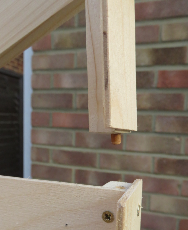
To locate the support I simply used a small piece of dowel as a peg, that sits in a hole at the top of the back-scene/wing support, it's enough to stop the lighting rig collapsing.


The legs are made in pairs and are bolted at the top to the back-scene supports, the bolts also act as pivots. These bolts will have washers and locking nuts, once the board is painted/ A third bolt is added to hold the legs in place, and will have a wing nut. Note the power socket is now in place too.


With the locking bolt removed the legs rotate 180 degrees and stow up the ends of the layout, the locking bolt is fitted back in another hole to hold them in place.


The photo below shows the layout from my eye height, it looks neat enough despite my dodgy woodwork, and takes seconds to set up and stow away. It should work well at exhibitions, which is just as well as it already has an invite...!


Now it all needs painting. And I need to get on with some buildings.