Showing posts with label Atkinson Walker Steam Tractor. Show all posts

Sunday, 27 September 2015

Finishing a pair of locos

It's nearly October, and I've just checked - it was June when I last posted about these locos! They've sat waiting for a few finishing touches, now with an exhibition looming it was time to tie up the loose ends and get them ready.


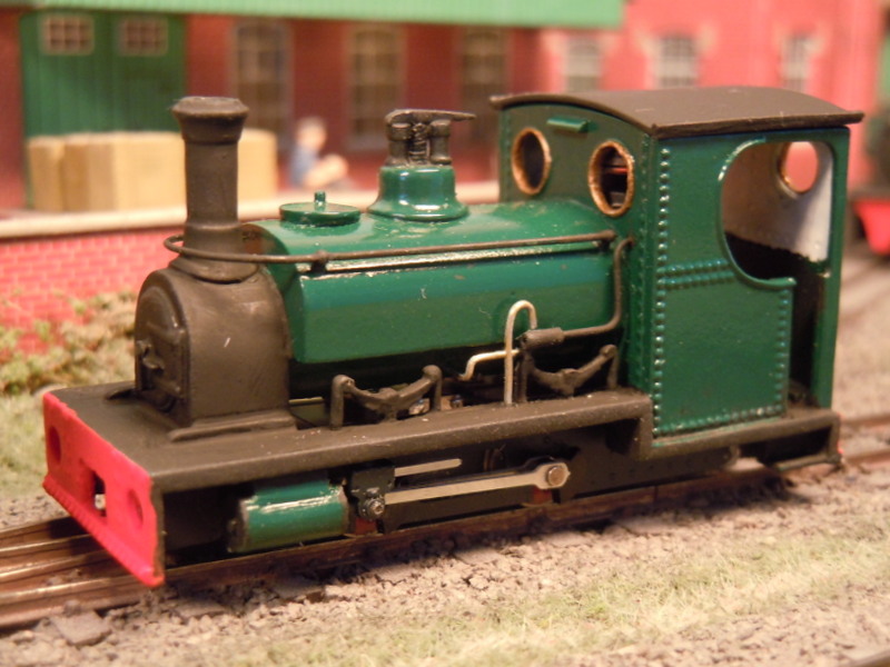
The Hunslet has been given a working "oily rag" look. This involves washes of acrylic paint over the loco - it seems not to stick to the shiny finish but working it in, and wiping off with a kitchen towel or cotton but eventually gives the right finish. Some subtle use of weathering powder is followed by a coat of Testors Dullcote - after all of which the over-shiny paint finish has just a dull sheen, and the loco has so much more character.


With a crew fitted the motor and flywheel are well hidden, the roof has been attached and couplings fitted. She runs well too I'm pleased to say.


With the Atkinson Walker I've gone for an even dirtier look, for a loco that is less cared for (despite being newer), or that has perhaps been recently acquired from a closed line. The same techniques were used, this time with the acrylic wash being brushed downwards in a rain-streaked fashion. This view shows the rudimentary interior: a representation of the cylinders and a some levers, along with a (leg-less) driver.


The exhibition is the Croydon Model Railway Society show next weekend - if you get there do say hi! I've got some more testing of couplings and stock preparation to do this week, and I'm hoping the new fiddle yard performs well.

Monday, 29 June 2015

Two Green Engines

With most of the painting done here's the Atkinson-Walker and the Hunslet, in different shades of green. Well, it adds variety!


The Hunslet uses Halfords Racing Green enamel aerosol, as used on some of my O14 i/c locos. It has perhaps a shade too much blue in it, but does look rather smart. The shiny finish will be toned down and lightly weathered shortly.


The Atkinson Walker uses Heathcote Ford Meadow Green. When weathered it should give a slightly faded appearance. I've not yet fitted the cab doors or interior "details", and I've noticed the wheels could do with toning down too.


Unfortunately painting black enamel over the acrylic aerosol has reacted, causing crazing. I've only seen this with with cellulose paint before, but I guess I could strip it off and re-paint with acrylic. It's only happened on the roof though, so right now I'm thinking of leaving it alone - it adds a nice texture, and with a little weathering it might look good.


Friday, 12 June 2015

Putting paint on the Hunslet

I've gradually been progressing the Hunslet towards painting. First the final details were added - the handrail and injectors. The handrail knobs were tiny and drove me potty, but I got there in the end. The injectors are made from nickel silver wire with a piece of wire insulation, following the prototype photos, fitted into holes drilled in the footplate, cab, and boiler, then super-glued in place. Actually right after gluing the left side solid I realised they might be better fitted after painting... so I left the right side off.


After a small amount of filling gaps and removing excess glue the body was cleaned and polished with a fibreglass pencil. However it doesn't look it in this photo as I then gave it a wipe over with a blackening solution. It doesn't blacken whitemetal, but it does dull it so perhaps paint will stick better.


Then it's out to the garage for priming, along with the Atkinson Walker Steam Tractor which has also been waiting for warmer weather! Halfords grey etch primer does the metal bodies, in about 4 thin coats from different directions. Standard primer was used for plastic parts too. This was followed by the main body colour - Halfords Racing Green for the Hunslet; a rather glossy finish but I'll deal with that later.


As seen here it has also received the first coat of black, though 48 hours later that doesn't seem to be properly dry so perhaps the paint has gone off? In addition the buffer beams have had a priming coat of white as red doesn't cover well. You can also see I've been scraping the paint off the injectors this side (the masking tape is to protect the paint behind), and that on the other side has been fitted.


Meanwhile, in between painting, the workbench has moved to other projects!

Wednesday, 4 February 2015

Atkinson Walker - Polishing Off

Work has continued on the under-frame of the Atkinson Walker, adding details like spring hangers, track rods (perhaps?), and those distinctive sand-boxes, made from pieces of plasticard, microstrip and microrod. I even added sand-pipes from brass wire, though they are barely visible.


You may also notice a change in the buffer-beams. The plastic ones were starting to bow already, and I thought they'd be vulnerable, so looked again at the ones on the etch. They seem to be based on the Clougher Valley loco rather than the Redlake one, and were too deep - and too wide too - so I trimmed them to size with a cut-out for the couplings. Although not quite the right shape they are pretty close now, so out came the soldering iron again. They are soldered to the bottom of the body, the square valences help to locate them. The under-frame then had the plastic buffer beams cut and filed away until it was a snug fit between the brass ones.


A bit more work with scraps of plastic made the odd shapes in the foreground - can you tell what they are for? A bit of time cleaning up excess solder and polishing the brass with fibreglass brushes and pencils, and I think it's ready for the paint shop.

Sunday, 25 January 2015

Atkinson Walker: Steps and Chimney

The Worsley Works etch included the steps, so these would be simple I thought. However it quickly became apparent there was an error in the etch. As you can see the lower step is easily folded up, and the upper should slot onto the vertical - but the vertical plate narrows in the middle, so the upper step is too wide to fit. A check of the drawings and photos confirmed that the upper step should be narrower, in line with the vertical plate.


The only solution was to narrow the step. One "end" was cut off, the step cut short to match the narrow part of the vertical plate, and the locating tab shortened. Soldering the remaining tiny pieces together was rather fiddly, and I've got rather too much solder in there, but it worked and looks OK as long as you don't look too closely! The steps were then soldered to the underside of the body, behind the valance and in line with the cab entrance, and the plastic chassis support lower footplate was trimmed to clear.


Next the chimney, which is not very clear from the drawings and barely visible in any photos, so there is some guesswork. I found some brass tube, 2.3 mm diameter which seemed about right, though the hole in the roof needed filing out to accommodate it. To give it the impression of some kind of cap I made a loop of brass wire a tight fit around the tube, and applied plenty of solder. A little filing afterwards tidied it up and gave it a more probable shape. Since it is barely visible in photos it can only just have protruded through the roof, so I set it low to the roof and soldered it in place from behind. The nice thing about this is the chimney can be seen continuing through the cab.


The other roof feature which is also hard to make out from the drawings and pictures - though it protrudes enough to be noticeable - is the large plate or raised section. I found a piece of scrap brass the right width, and about 0.5mm thick, which was cut to length and curved to match the roof profile. Soldering it in place really tested the capability of my 25W Antex iron though!


The roof features and the steps really do start to give the model some character. I think that's all the soldering done now, so the body is being cleaned of flux, and I can add the final details to the chassis.

Thursday, 22 January 2015

Atkinson-Walker: More Soldering!

At the weekend I'd managed to pick up some square section brass for a more reasonable price than I'd been able to find it at the Bognor show. This is just what I'd been looking for to make the valance along the bottom of the body, though at 1.6mm square it is slightly over-size it looks fine. This was carefully cut to length and soldered on.


With that done I could solder the upper body in place, taking great care to get the pieces vertical and fitting together. The roof took ages to roll, being quite a thick piece of brass - perhaps I should get some rolling bars, but the fingers/pencil/carpet along with holding one edge in a vice got me there eventually. Those mini pegs came in useful again, soldering the roof in place was easier than I'd feared.


The brass section valences actually do lot to keep the body rigid, particularly through the doorways, which helped when adding the roof. They also help locate the under-frame (which needed a little filing to fit nicely) and hides the lower plastic footplate.


So I couldn't resist posing the assembled loco on the layout. It is certainly large - not surprisingly for a 3' gauge loco modified from a Standard Gauge design - however it isn't so far off some larger stock that I have. I'll have to compare it to a GVT tram loco, which are quite bulky.


There's still lots to do. The drawings show a large plate or raised area on the roof - it's barely visible in photos, as is the top of the chimney, so I'm not sure what these should look like or how to make them. They will add a lot to the model though. I also need to solder on the steps, then it's on to detailing like the water filler cap (again it's not visible in pictures), cab doors, and perhaps some basic interior detail. Brass etched buffer beams are provided, but to the profile of the Irish loco rather than the Redlake one, so I've started cutting some from plastic which will attach to the under-frame, and need to allow for couplings. The under-frame also needs sand-boxes and a few other details to finish.

Wednesday, 21 January 2015

Atkinson-Walker: Making an Under-Frame

When I last posted about the Atkinson-Walker steam tractor I was pondering how to make the under-frame, which is not included in the Worsley Works "Scratch-aid" etch. I found some wagon under-frame mouldings in the bits box, I think from an W&L open wagon, and came up with a cunning plan.

I started by opening out a recess above the spring, which gave space to add a few extra leaves from micro-strip, a fiddly job but now they look like they could take the weight of a loco. The W-irons were cut away, and the axle-boxes rounded off slightly, as per an approximation of the drawing. The wagon frame was 1mm shorter than the wheelbase of the chassis so I cut and spliced in a piece of 40 thou, with a splice behind. The notches in the top are cut to clear lugs below the motor. In the photo below one frame is prepared, the other is just started on...


Then on to the outer frames. I'd remembered to take the book to work and photo-copy the drawing at 82%, bringing it to 4mm scale, which makes life easier. I did a few copies while I was at it, allowing me to cut out the frames and stick them to some 20 thou plasticard with a few drops of solvent. It is much easier than all that marking out, a few cuts and I had the basic shaped of the side-frames, there's a mark where the paper was stuck but I'll just stick that on the inside. 


Micro-strip was added to the frames according to the drawings and pictures, and the wagon-frames with axle-boxes and springs positioned behind. A dummy lower foot-plate was also cut out, as seen above. The nearest side-frame shows the rear with the wagon sole-bar, this sits just below the motor with notches to clear the plastic motor support brackets on the chassis. The 20 thou frame sits against the side of the motor, which should give the right ride-height. It's now clear why it was useful to have the springs and axle-boxes from one piece of plastic - there is nothing to support them except from the frame above, strictly speaking there should be a gap above the springs too but the lack of that won't be visible!

Holes were then drilled through the plastic lower footplate and the brass footplate of the body for the bolts - I decided one at each end, off-set to allow for couplings to fit centrally. An M2 nut is soldered above the floor, by threading a Vaseline covered bolt with another nut from below and tightening. A little flux applied around the nut with some small pieces of solder, then apply the iron. In theory the Vaseline stops the bolt getting soldered too, and it did - but on the second one some solder got into the bolt thread between the nut and the brass sheet. I managed to unscrew the bolt though, and as it didn't need to be so long, just cut off the clogged end!


Then the side-frames and lower foot-plate were joined with 40 thou plastic cross pieces, that are fitted to just clear the ends of the chassis. In the picture above you can just see a plastic "lug" is bonded to the inner face. This fits into the notch in the end of the chassis, it has a chamfered top edge but flat sides and bottom. The chassis is fitted into the frames from above, and with a screwdriver gently prising the cross-members over the ends of the chassis until the lug slots into the notch.


The frame/chassis assembly can then be bolted to the body from below as shown. A valance will need to be added below the body, which will disguise the edge of the plastic lower footplate. From above you can see I added some brass "M" shaped brackets from spare etch, which press on the top of the chassis. Actually the plastic lugs previously mentioned do the locating so these aren't really necessary, but may add some strength. Brass brackets also press against the motor sides to hold the chassis/body vertical.


The frames look OK, axle-boxes line up (reasonably), and ride height matches the drawing, so all good to continue with the build! I've yet to add buffer beams and some details to the under-frames, as well as the valance mentioned, but now I can progress the body too.


Monday, 5 January 2015

Atkinson Walker Steam Tractor

So here's a project I've already got on the go, albeit progress has been rather slow the last couple of months. I had a Halling chassis and having read the book on the Redlake Tramway, I thought an Atkinson Walker Steam Tractor would be an interesting model. These were vertical-boilered chain-driven locomotives, like the better known Sentinals they used road-vehicle ideas from the time, to make efficient and cheap shunting locomotives. Most were standard gauge but two were built to 3' gauge - the more famous one ended up on the County Donegal Railway in Ireland, where later rebuilt as a Diesel it was named Phoenix. More about that here, where I found this picture of the Redlake loco.


I'd wondered about a scratch-build in plasticard, which shouldn't be too hard apart from the curved corners. I might then have scaled down the body slightly from the 3' gauge versions, however looking at the dimensions I figured that although large, I could just about get away with it in 009. So to make life easier I picked up the Worsley Works scratch-aid kit at EXPO-NG.


As usual for these kits there's some etches for the body - and that's it, no under-frame parts, details, or instructions. The parts are obvious enough though, once I'd figured that the half-etch rebates in the top and bottom of the sides were to go at the outside, and allow beading to be added. So first I cut a hole in the footplate for the chassis to fit, then with the sides carefully curved around and soldered to the footplate and the tank-tops I found some 0.5mm brass wire that fitted into the rebate.


Bending to size, fitting, and soldering the wire was not a little fiddly! Some miniature clothes-pegs (no it isn't a 16mm scale model) from my wife's card-making oddments came in useful.


So the lower body looks OK, though there may be some more cleaning up of excess solder. I've got hand-rails to add in the doorways, then the upper body (windows) and roof to solder on. The roof will restrict access, though the body will be floppy without it, so I need to figure out what's going on below and inside first!

I have added a couple of brackets inside from scrap brass to centre the chassis in place, but I haven't yet figured out how to attach it. I tried making up brass clips to fit into the ends of the chassis, but that's tricky. I also need to make the underframe, which may be narrower than the motor, so I'm thinking of making frames and buffer-beams as a plasticard sub-assembly to which the chassis clips, and can be bolted to the body. Those springs are quite distinctive, any suggestions for suitable mouldings?