Saturday 21 February 2015

Outside Framed Hunslet

A while ago I posted that I'd got hold of a Minitrains outside-framed chassis (from their Fiddletown & Copperopolis tender locomotive) and wondered whether it would be suitable for a Dinorwic large Hunslet. Unfortunately the distance from the motor to the cylinders is too short and would put the cylinders too far back from the smokebox.


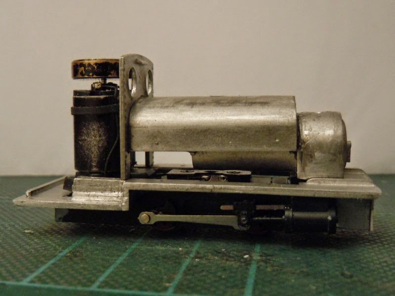
However undeterred I got a new kit for the "Cackler / Jerry M" Hunslet (by Five79) and set about adapting it to fit the chassis! The dummy run trial below shows the smokebox set further back to line up with the cylinders (well nearly), and the saddle-tank scored with a line 4mm from the rear where it will be shortened. I'd already carefully removed the filler cap from the casting, which can hopefully be re-used, and the other round plate on top of the tank (purpose unknown!) was filed smooth. The footplate has the hole for the motor opened out towards the rear a little.


The chassis has some modifications. The plastic "footplate" around the motor is cut away along with a section of the rear frames, allowing the kit's footplate to sit on it, and some plastic "pegs" glued just below the motor that protrude just above the kit's footplate to hold it down. At the front of the chassis the extended keeper plate is cut short and a 2mm hole drilled for a fixing screw. On top the plastic plate/clip has it's vertical "wings" removed to clear the boiler.


The whitemetal footplate has been shortened by about 3mm, including the dummy frames below, and both the front of the footplate and the bufferbeam filed to a 45 degree chamfer to fit the buffer beam better (that's been done at the rear too). A mounting plate for the chassis has been bent up from brass, with a 2mm hole drilled and a brass nut soldered on. This will be glued into the front of the footplate/frames casting.


The boiler, smokebox, and cab front are glued together so time for a trial run on the footplate and chassis. The cylinders are still a little too far to the rear but I hope to disguise this further, otherwise all looks promising so far.


Friday 13 February 2015

Train Set Features

I thought I'd post a few more pictures of my Son's train set, last seen when I'd just finished the track-laying and wiring. The few buildings so far are Hornby, most of which came from my childhood train-set, they are nice and robust which is ideal for this situation. They are stuck to the board with impact adhesive for when the board is folded up.


A busy view with some favourite trains on view! Lots of brick walling will be needed.


I found my old car transporter wagon and loading ramp, which adds a bit of fun.


Joshua got given a PECO turntable for his Birthday, so we spent a little time putting the kit together. I'd left enough space for it, so it was simply a case of mark out the circle and cut out with a jig-saw.


The kit is easy enough to assemble, so soon it was in place and having the tracks laid. The turn-table track takes it's power from the approach track, but I have yet to power the spur tracks - I'm sure there is a clever way to power them from the turntable position but I'll probably use a rotary switch.


Finally - in use! That track to the right needs a bridge now...

Wednesday 4 February 2015

Atkinson Walker - Polishing Off

Work has continued on the under-frame of the Atkinson Walker, adding details like spring hangers, track rods (perhaps?), and those distinctive sand-boxes, made from pieces of plasticard, microstrip and microrod. I even added sand-pipes from brass wire, though they are barely visible.


You may also notice a change in the buffer-beams. The plastic ones were starting to bow already, and I thought they'd be vulnerable, so looked again at the ones on the etch. They seem to be based on the Clougher Valley loco rather than the Redlake one, and were too deep - and too wide too - so I trimmed them to size with a cut-out for the couplings. Although not quite the right shape they are pretty close now, so out came the soldering iron again. They are soldered to the bottom of the body, the square valences help to locate them. The under-frame then had the plastic buffer beams cut and filed away until it was a snug fit between the brass ones.


A bit more work with scraps of plastic made the odd shapes in the foreground - can you tell what they are for? A bit of time cleaning up excess solder and polishing the brass with fibreglass brushes and pencils, and I think it's ready for the paint shop.