The last stage of the animated playground construction is to wire it into the layout, with a switch so it is easily started and stopped. There was space on the control panel, so I edited the Word file I'd created it in to add a couple more switches.
I actually create two copies of the panel, one has outlines of the switch positions to ensure the design allows for the space they need and when printed out marks where to drill the hole, the other is the printout that is used for the panel. The playground switch has been added bottom right marked "play", you can see I have also added a switch for lighting as I plan to add platform lamps at some point. The holes in the paper were opened out with a scalpel after placing over the drilled aluminium panel (see below...)

The existing panel was removed from the layout and all the switches were removed, the clear plastic front and existing print-out taken off. 6mm holes were drilled in the aluminium panel for the new switches. This is the rear, upside-down (i.e. flipped over towards the camera) so the "light" and "play" switches are top-right, the sharpie labels help me remember which switch goes where. Just above the switch hole (so below in the photo) is a 2mm hole about 1mm deep used to locate the "tab" on the switch washer, this stops the switches rotating in the hole.
With the new printout placed on the aluminium and the clear plastic over the top, the track switches were reinserted, then the holes for the new switches opened out through the plastic with a scalpel before fitting the new switches in place. Since point motor switches are bare metal and the only colour caps I had in that didn't match colours already in use were yellow, the new switches have yellow caps!

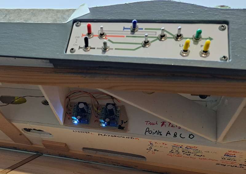
The playground motors are fed via a voltage regulator, these little circuit boards output controlled DC from a range of AC or DC inputs, and are cheaply available on ebay (something like this although I've had these in a while). In this case the input uses 16V AC which is provided from my transformer packs to the layout though the 6-pin DIN connection I have standardised on, removing the need for additional specialist power supplies, and the screw potentiometer is adjusted to give about 3V. The output from the regulator goes to the two motors via the panel switch - simple. While at it I put a second regulator in for the future lighting, which can be set to a different voltage. The regulators attached with some tiny screws to an offcut of MDF glued to the foam-core baseboard.

I attached a choc-block connector to the underside of the playground sub-base with hot glue and wired the motors to it - there are enough connectors to allow a resister to be added to either motor if ever needed. The playground can then be removed by unscrewing the terminals to the two orange wires.
That's all the practical work done, I just need to finish the playground scenically now.


No comments:
Post a Comment