Signal boxes are all very well for standard gauge railways, but let's face it only the larger and better equipped narrow gauge railways had the need (and cash) for such luxuries. Many lines managed with levers next to each point, although for those carrying passengers the regulations on facing point locks means ground frames were often use. I'm modelling Hexworthy in preservation so of course facing point locks would be needed, though as a terminus of a single line signals would not be necessary - movements being controlled by the single line token. So while some preserved lines have gained signal boxes in later years, I thought Hexworthy could manage with a couple of ground frames - the single line token equipment would probably be installed in the station building. The two points on entry to the station would need facing point locks, the loco release point probably does too since it is against the platform and a departing train could have coaches over it.

A Wills kit makes up a delightful pair of ground frames (with parts left for a couple more). The small one has levers for a point and its point lock, the larger the same for two points. The problem is, now they will look odd without some representation of the rodding and cranks that would connect them too the points. Wills do a nice kit for the rodding, but I only need a few inches...
The little frame is right next to the point it serves, although at right-angles so as not to obstruct the yard. I made up some planking to "hide" the crank and rod to the point next to it, and protect it from feet, but the rod for the point lock comes out to a crank. The rod was made from 0.5mm brass rod - I know it was often square, but the GWR used round and Hexworthy is in GWR territory, anyway plastic strip was too weak and flexible. The crank is an L-shaped piece of plastic with slices of microrod for bolts, stuck on a block of plastic.
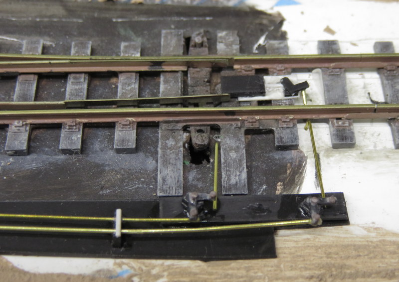
The larger frame controls two points. I made up the rodding on a sheet of 20" plastic, which will be buried by the ballast. The brass wire rodding is supported in stools made from 40" plastic pieces end-on, with notches cut in the top for the wire, and a strip of microstrip over the top - it doesn't bear close inspection, but I think gives a reasonable impression.
The close-up shows a couple of cranks made from scrap plastic in the same way as before, as is the facing point lock - a block of 40" plastic for the lock mechanism, a "plate" of 10" plastic, and another crank. The rod to the point lock is actually in two parts, the nearer being an L-shape with the short leg punched vertically into the foamcore baseboard, the same is done for the tie-bar operating rod. The point is in reality operated by a point motor below the board, this rodding is entirely dummy.


1 comment:
8Hello Michael,
Have to say impressed with your attention to detail and even more so with your scratch built point rodding. Nice to see this level of detail and I guess on a smallish layout it is not so daunting to 'rod' a few points as it might be on a large layout with many points. Just another of the advantages of smaller layouts. Should be a great project when complete.
Woody
Post a Comment