Monday, 7 August 2023

Wiltshire Group Open Day - Pewsey 2023

Last Saturday I found myself at a loose end and realised the Wiltshire 009 group were holding their open day at Pewsey. Google told me that was about 2 hours drive, but there was a long list of layouts, so I figured it was worth the trip. It was. Here are a dozen of the layouts, but I have missed out several smaller layouts...


Dithering (1:55 scale, 9mm gauge) - Christopher Payne. A new under-construction project representing a 20-inch gauge railway. 


Keindorf (HOe) - Tim Tincknell. Unmistakably alpine. 


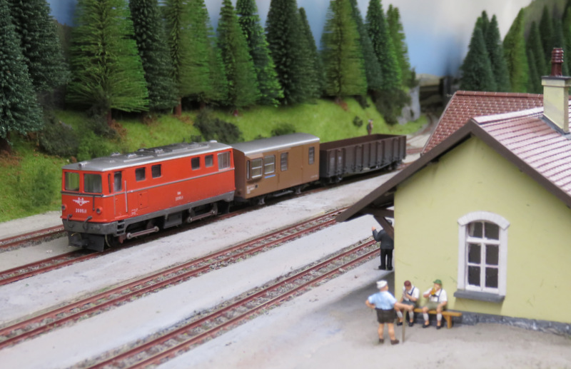
Kaninchenbau (HOe) - Iain Morrison. Unashamed alpine rabbit warren with computer controlled operation. Faultless running and always something moving. 


Newton/Goat horn (009) - Graham Kean. Atmospheric might-have-been set in Purbeck, Dorset. 


Woody Lane (009) - Steve Fackrell. 


The Yard (SM32) - John Bruce. A large scale "Inglenook" under construction with radio control. 


At the bottom of the garden (1:24) - Clive Harman. Using (I think) N-gauge as a garden line. 


Greensplat (009) - Richard Williams. Using the "caricature" 3-D print models of standard-gauge diesels shrunk to narrow gauge, designed by David Malton. 


Bryn a Felin (009) - Matthew Kean. Recognisably Welsh Highland Railway inspired. 


Tan Y Bwlch (009) - Brychan Watkins. The instantly recognisable Ffestiniog Railway station. 


Wheatstone Bridge (009) - Miles Bevan. Simple 009 layout, nicely done. I hadn't noticed the name and it's pun until later. It is hard to resist. 

Hawkridge (009) - Chris Mould. Another under construction layout in an urban setting, 

An excellent day, and great to meet people too. 

Tuesday, 1 August 2023

Bagnall and Kerr Stuart detailing and ready for painting

With the chassis now sorted, I could crack on with the build of the little Narrow Planet Bagnall kit. I'd already primed the 3D printed body and cleaned up any lines (mainly the boiler and smokebox), and primed the etched parts on the fret too. I decided to fit Microtrains couplings, so cut square holes in the body print in the appropriate places, and rather than try and modify the etched buffer beams, I cut new ones from 20-thou plasticard using the etched one as a template. These and the etched tank sides and cab front and rear were superglued in place, and the chimney, dome and clack valves added too. The wire cab-side handrail was added as per the instructions.


So far all pretty straightforward, but it looked rather bland. I dug out my copy of The Rye and Camber Tramway (Laurie Cooksey) and some pictures of Polar Bear for inspiration for details. I added some wire pipework to the clack valves, probably not correct but impressionistic, plus a blower pipe on the left side, and a representation of a reversing lever on right. I made a crude impression of a lubricator from a sewing pin and a slice of wire insulation to fit behind the chimney, and a whistle from bits of plasticard and plastic rod to fit to the front of the cab. I use a piece of fine wire to make an impression of the smokebox door handle, it's not great but looked better than nothing. 


I also added some cab steps folded up from brass, Camber and Polar Bear don't have them but the slightly larger Victoria did, they should have a "waisted" vertical but by cutting skills don't run to that. The chassis slide bars didn't have a vertical support at their rear end, so I made one from 20 thou black plastic, a fiddly job! You can see I've filled any gaps with green Squadron Putty, including where the etched cab front and rear meet the body. The footplate had developed a slight curve at the front and in attempting to straighten it while fitting the front bufferbeam I broke the corner off, fortunately it superglued neatly in place and the filler hid the gap. The loco body then got another coat of primer, another rub back and filler touch-up, and a final coat of primer.


The Paul Windle Kerr-Stuart has also had some attention. The cab rear looked to have been dislodged and glued back in place, or slightly out of place. I have cleaned up the glue as much as possible, relocated the uprights and supergued them. The body was cleaned up with a damp brush, and even scraping the accumulated crud with a screwdriver, to clean it up ready for painting. The tank sides were lightly rubbed down with fine emery paper where the paint had become scuffed. 

The sanding gear operating rods were repaired. I also added some cab side handrails as they seemed to be lacking, but otherwise the detailing looked fine. It was then sent for a coat of primer, which showed up a couple of gaps needing a little filler, and some spots needing a rub-down, before a final coat of primer.

Both loco bodies are now ready for painting...

Saturday, 22 July 2023

Amberley

The Amberley Museum hold an annual rail gala weekend with lots of narrow gauge trains running and a model railway exhibition in the railway hall, and as usual the Sussex Downs 009 group support with our society stand, which I helped with today. 


We have a small demo layout and a showcase to show what is possible in 009, and a modelling demo to show how, and answer questions. Here's Tim and John. There were a handful of layouts and traders, although it's not a big exhibition. This event is unusual in that it is both narrow gauge railway interest and a general public/family attraction, so a real mix of visitors, and the model railway exhibits in the railway hall are a side attraction to the rest of the museum and the full-size railway goings-on. That means at times it can be quite quiet in the hall, so having some modelling to do is useful! 


Outside amongst lots of interesting 2-foot gauge industrial trains, it was nice to see three of the four Thakeham locos, The blue Hunslet was in use on demo freight trains. 


With Polar Bear out of service for a boiler overhaul an alternative yellow loco was on passenger duties, this relatively large and modern Baguley Drewry. I was lucky enough to have a cab ride, thanks to Gerry Cork (seen driving) and Pete Smith. 


The cab is spacious and comfortable, if a little noisy, and the view through the large windows is excellent. Here's a view over the nose with Peter waiting. From above, it's clear the bonnet really needs a repaint! 

Always nice to see Peter in steam, a charming loco. A pity the rain came in by the afternoon, the demo freight trains had to stop as they slipped on the wet rails, and the afternoon loco "calvacade" was cancelled, not that many would have stood around in the rain to see it anyway. 

Monday, 17 July 2023

Reviving a Minitrains Porter

Some time ago I started a Narrow Planet kit for a little Bagnall tank using a Minitrains Porter 0-6-0 chassis. The Porter body had to be removed, which involved cutting part of it away from around the motor as I recall, but after having done so the chassis didn't run smoothly. I then noticed the motor looked wonky, and on closer inspection I found one of the retaining screws had a stripped thread and didn't tighten. After some frustration I put the kit away to think about what I could do about it.

Having made some progress with the Kerr Stuart Haig chassis I figured I'd pull this kit out to see if I could revive the chassis too. The first discovery was that the two screws that hold the top plate of the chassis down are the same M1.4 thread as those that hold the motor, although very slightly shorter and countersink head. However, one could be carefully screwed into the motor in place of the stripped screw, the motor thread is damaged too but not so bad that the new screw couldn't bite. This is made far more difficult by wheels being in the way preventing a screwdriver being lined up straight. The old screw went into the top plate of the chassis where it is not under strain. 


The motor still looked wonky, and the chassis still ran badly, jerking and clunking. With the screws backed off slightly the worm slipped. I tried adding packing (10 thou plastic) under the front of the motor tilt it back slightly, but then it wouldn't run at all. I then rotated the motor 180 degrees, which seemed to result in less of a lean - I've no idea why. The chassis was still jerky and clunky. 

With the motor removed it span freely under power - but the chassis didn't roll smoothly, with a definite clunk once per revolution. Gently, the rear crank-pins were prised out to free the con-rods, but the clunk remained. Finally I had to accept I would have to do what one should never do with these chassis... open it up!


Tiny screws, tiny gears, even tinier washers. Scary. Anyway, on close inspection I discovered one of the gears (on the middle axle) has a damaged tooth. These teeth are tiny so it is very hard to see, but just visible in the picture below - look for the unequal gap between teeth. 

I have no idea how this can have happened, but the real question is how to fix it. I can't fix the gear, but I could swap the axles so the damaged gear is at the front, and remove the idler gear, leaving the just rear and middle axles powered. Of course, getting the two axles in place with the idler gear and their crank pins aligned was rather tricky, but I suppose the same challenge with 3 axles and 2 idlers is even harder. Fortunately it all went back together in the end, and the chassis ran smoothly as a 2-4-0. Encouraged, I then re-attached the coupling rods and connecting rods, first omitting the middle axle crank pins to drive the front axle from the rear, the middle axle appeared to rotate with it's crank pin holes in line so I added the middle pins too. Somewhere along the way one of the tiny washers from behind the coupling rods pinged off the tweezers into space, but it seems to manage just fine. 

Yes, amazingly after all that work, the chassis actually works, and appears to run as smoothly and sweetly as you'd expect a Minitrains to, despite it now lacking an idler gear and relying on the coupling rods to drive the front axle. 


You see from the video the body is placed on. Before giving up on the chassis I'd spend some time smoothing the visible parts of the 3D print and given it a coat of primer. I added another coat, but found the lightweight body blew away from the spray can! It needs weight anyway to balance the chassis and aid pick-up and traction, so I added some lead. The "Swiss rolls" are slid into the boiler, and the flat pieces into the small side tanks, wiped with a little contact adhesive to hold them in place. As you see from the video this is enough to aid good running. 

Chassis problems fixed, I can now continue the build of this dinky little loco. 

Sunday, 16 July 2023

Reviving the Haig - Part 2

Today I decided to investigate the running problem. The chassis seemed to run OK out of the chassis, but when I put it under load (holding it back) the worm started slipping on the gear. On closer inspection I realised the motor (and mount was twisting to the side, and could slip off the gear. After a little thought, I moved the motor over with another piece of 1mm plastic to the side of it. I also superglued the brass strip to the plastic packing beneath it, which is a tight fit between the "springs" on the tops of the frames so should help to prevent twist, and having noticed if the bolt was tightened too much there was a short, I stuck Sellotape on the underside of the brass as I suspect it can touch the springs. 

That improved things slightly and the loco ran up and down OK, but again if run under load the motor started slipping. This time I noticed that the motor could lift off the brass mounting plate. It's stuck with contact adhesive which remains a little rubbery, and it may not be helped by the motor which does run quite warm, so allowing just enough "give" for the gear to slip. 


After some more thought I figured the motor needed to be physically held down, and decided the easiest way was with a wire that could be tensioned. I drilled a hole in the brass each side of the motor and looped a wire through, twisting the ends together. I tried a copper wire but it snapped, then found a steel wire in my useful-wire-bits tin which could handle the strain, the ends were twisted with pliers until the motor was held down tightly. Of course the wire over the motor required some of the lead in the boiler to be ground away for the body to sit flat, and the twisted end needed to bent over and tucked carefully into the body when fitting the chassis, but it seems to work.

Running is still not quite as smooth as I'd like, there's a little hesitation at times and it can be prone to the odd stall which is odd given the 6-wheel pick-up all seems to work fine and I can't feel any binding in the chassis, although after a little more lubrication and when warmed up it seems acceptable. Perhaps a flywheel will help if I can find one to fit (needs to be 10mm diameter, 3mm deep, and 1.5mm shaft). 


Saturday, 15 July 2023

Reviving the Haig

 The Haig is in a bit of a sorry state. The body looks tatty, and appears to have had the cab rear fixed after a break, I'm sure this can be tidied up in due course. 


It looked a little nose-down to me too, an extra piece of plastic packing under the smokebox sorted that. Of course then the bolt which holds the chassis to the body - which was barely making a couple of turns into the nut anyway - was now too short. Fortunately I found another of the same thread (well it fitted the captive nut), but too long - so that had to be cut down with the dremel.

The plastic body was very light, although it did have a piece of lead under the read half of the boiler. I fitted a "Swiss roll" of roofing lead into the smokebox, and managed to slot pieces into the side tanks, the left side tank had only small gap at the bottom which I opened out slightly and "posted" in slices of lead wiped with contact adhesive. 

I fixed the motor to the brass mount with contact adhesive, which holds it securely enough, and wired it to the chassis frames. The brass motor mount is held in place by the bolt at the front, and a wire "finger" that slots below a lip on the right chassis next to the worm gear - this stops the motor rising up, at least in theory. 

So, does it work? Yes, but... it's a bit jerky, and the worm must be climbing the gear and pushing the motor up as it really grinds going forwards (smoother backwards). Sometimes it even stops and spins the motor. So much for that wire finger, I wonder if the brass can twist? It may not help that the drive is a little crude and has a fair amount of friction, even after a little lubrication, although there is no binding. I need to rethink that motor mount...

Saturday, 8 July 2023

Bargain bin Kerr Stuart

At the SWING show a few weeks ago one of the traders was selling some second hand 009, including some interesting "projects". I restrained myself to three...


In the centre is a Wickham Trolley etched kit. I doubt it is practical to motorise in 009, I'm thinking it will be an interesting scenic item for Hexworthy. 

On the right is what appears to be a 3D print with (I think) a Meridian chassis. Other than a broken wire, one of the layshaft worms isn't meshing with the axle, yet there's no obvious scope for adjustment. For £5, this is worth a play, 

Most interesting is the loco on the left. It's a Kerr Stuart Haig class I believe, I had assumed a scratch-build at first glance, on closer inspection I recognise the work of Paul Windle. The chassis is an adapted Bachmann, it looks like Paul removed the motor from the rear overhang and mounted it backwards over the wheels using a brass mounting, but the motor is missing. In the box with it were two coreless motors and a Mashima, the latter with a worm already fitted. Also just £5, this is a bargain even as a static model. 


The unmotored chassis rolled, but there was a slight bind once per wheel revolution, and it was full of crud. In the end I decided to strip it, this involves removing the stub-axle wheeels, undoing a screw each side, and removing the metal sides to give access to the geartrain in the plastic. The whole lot were wiped clean of accumulated oily dirt. All the gears look good with no sign of splitting. 


The metal sides work as split-frame current pick-up, but wire wipers had been soldered on (see bottom frame) so perhaps relying on the stub axles wasn't reliable. However, there's not much space behind the wheels and I wondered if the wire was putting too much uneven pressure on the wheels. I replaced them with a strip of phosphor bronze (as seen on the upper frame), although the size of the sideframe was a challenge for my 25W iron. 

Re-assembly required the wheels to be pushed in place in line with each other, and quartered to the other side. Fortunately since the axles are gear driven, and there's a fair ammount of slop in the gears and the coupling rod, this isn't critical. Even better, now the chassis rolls without any binding, it's not super-free running but it is smooth. 

The next challenge is fitting a motor. I'll use the Mashima as it looks a good fit. 

Option 1: I guess I could stick it to the brass plate with a lump of araldite or sealant, crude but it might work. It's only held by the screw at the front though, and located by the wire under the plastic lip at the rear of the chassis - but that's how the original motor was fitted. 

Option 2: I could make up a new motor cradle, from brass or plastic, also held by the screw at the front. It would still probably rely on glue to hold the motor but perhaps could be a closer fitting shape.

Option 3: I could use the screw holes on the front of the motor to screw it to a vertical brass plate, which could itself be stuck to the chassis block via an L-shape at the bottom, perhaps also with a fold under the lip. This allows for motor removal and doesn't rely on the bolt at the front, but may need more precision  than I can manage, I don't have motor screws, and the worm is on the wrong end of the motor!

I should note that the slide bars and motion assembly is held to the top of the chassis by the brass motor mount, so whatever I do needs to hold that in place too.