Thursday, 24 February 2022

River Banks

 When I visited Devon last summer I got some pictures of the river Dart at Hexworthy. 


My model can only include the riverbank, and the very edge of the river, which means capturing the feel of this place will be a challenge. The river banks are a challenge in themselves, consisting mainly of large boulders. 


Some of those boulders are pretty huge - the size of a car - while others are small. While some are rounded, some are quite angular.


A while back (actually nearly a year ago!) I cast boulders in plaster using a Woodland Scenics mould. The castings look great, but are somewhat regular in size and roundness. 


So I made my own boulders from DAS clay. These are not so much sculpted as carved, like chunks of cheese, keeping an angular appearance hopefully reminiscent of the large angular blocks seen in the photos above. The DAS blocks were cut to sit on the riverbanks but give the impression of being embedded in them, but the cast plaster boulders were set into the riverbank by cutting recesses into the scenery. 


As well as the riverbank along the front of the layout, I lined the stream with (slightly smaller) boulders.


Rocks and boulders come in a range of sizes though, so smaller ones are needed. These were added from a pack of Woodland Scenics "Coarse Talus" - I've no idea what that is supposed to be, other than small rocks. 


These were added around the larger rocks, hopefully in a random and natural way. I think the mix of sizes and shapes is quite effective, but of course the colours are not - cream colour clay, grey plaster (I'd added paint to the mix), and brown rock.


Out with the paints then. I started with a grey over the clay and plaster rocks, with a thin wash over the Talus rocks. I then stippled on a dry brush of a pinkish-grey shade, and of a yellow. Actually, the painting process took a few rounds of washes and dry brushing, and finally a dusting of talcum powder over the damp paint. 


The colours are now more unified, but keep some variation, and the Talus and plaster casts keep their texture. I've also mixed up some more tile grout and back-filled the banks up to the back of the boulders to set them in. In due course grass and undergrowth will come right down to and overhanging the boulders. 


The smaller stones in the bed of the river and stream are from another Woodland Scenics bag, of fine Talus. These have also been given a thin wash of grey paint but don't seem to have taken it as well as the larger rocks, though it has toned down and darkened them. 


There may be more I can add to the rocks to represent the lichen and moss seen on them. I now also need to think about how to model the water. My options are:
  • Use a commercial water product - but I've no experience of these, and the river is very shallow with a low lip at the baseboard edge - I'm not sure how well it would be contained
  • Use gloss modge podge as I did for Loctern Quay - while this worked well for a painted "water" surface, any depth would take a lot of coats and I don't know how well it would dry if put on too thick
  • Given the colour of the water in the photos above, good old yacht varnish might be a good bet. I used this on a layout I built in my teens, the main problem was it creeping up the banks which didn't look great. 

Saturday, 19 February 2022

Festival of British Railway Modelling Doncaster

Last weekend I took Loctern Quay all the way to Doncaster for the Festival of British Railway Modelling exhibition. While it was a long trek it was good to be at a big show, and despite its small size the layout attracted a lot of positive comment. Many asked about the buildings, and I could point out the nearby Petite Properties stand!


Here's my friend Tim Sanderson showing how not to operate the layout by standing right in front of it, though to be fair this was a quiet moment and Tim was learning how it works. Tim had brought his own small 009 layout The Old Quarry - we fit the two layouts and three of us in one car


The Old Quarry is an attractive scenic layout with a simple track plan, and some ferociously tight curves!


A big show such as this can host large layouts, but I am always drawn to the small layouts, such as Ladmanlow Sidings, which is modelled on the Cromford & High Peak railway. This shows that a simple layout with simple but effective scenery can ooze atmosphere. 


Leysdown, an EM gauge layout by Adrian Colenut, is another layout that has a simple concept beautifully executed. 


Some of my favourite layouts in the show were in smaller scales. Blueball Summit in N-gauge shows an incredible level of detail for such a small scale, with consistency and effective composition, and well-modelled trains too. 


Sandy Bay was another remarkable N-gauge layout, this time set at the seaside with a harbour and fishing village as a backdrop to the viaduct. This end-view gives a different perspective to the attractive scene. 

Heybridge Wharf makes effective use of the unusual scale of 3mm:ft in a harbour scene, with fine modelling of a sailing barge as well as the buildings, and of course the trains themselves. 

So the long journey was worth it for a good show, it was nice to see and speak to lots of visitors, and good to see Phil Parker and Colin Peake. 

Tuesday, 8 February 2022

Exhibition prep: Loco crews, glazing, and couplings

Loctern Quay will (Covid permitting) be at the Festival or British Railway Modelling in Doncaster next weekend (12th & 13th February). The last week or so I have been checking everything over, test-running the locos and stock, dusting the layout, and any odd jobs that get put off. 

One such job was the couplings on Toby, my Paul Windle built tram loco, which have never been reliable at uncoupling because the iron tails touched the cow-catchers limiting their throw. Recently I'd picked up a new pack of Microtrains couplings in a sale, but could only get the 1016 type rather than the 1015's I usually get, the only difference is that they are a little longer in the shank.


The difference is clear in this really close up photo (the lines are 10mm apart). It struck me that this extra length could be useful for Toby, so I swapped the existing 1015-type couplings for a pair of 1016's. 


As can be seen the tails are well clear of the cow-catchers, and don't make contact under their full movement. While tackling odd jobs Toby has also had a couple of other upgrades: I've finally glazed the side and end windows (the doors are unglazed), and fitted a crew, both helping remove the empty look.


I crewed three locos actually. A tip from Phil Parker is to superglue them to a coffee stirrer during painting. On the left the two for Toby are Preiser HO figures from their truck drivers and passengers set, stuck to 40 thou plastic bases to give them extra height and provide a means to stick them in, the chap front-left has had his arm repositioned. The other two on the back row are also Preiser, this pack seems to include a lot of arm waving so Mr Teapot has also had an arm rotated at the elbow. The front right and centre are from the ever useful Dapol range, slightly modified, both have lost an arm and half a leg...


Fitted to these Minitrains locos the smaller Preiser figures are useful for the Decauville, while the taller Dapol figures are needed for the slightly exaggerated cab of the Bagnall but needed trimming to snuggle up to the motor, and one needed his coat thinning to fit the narrow opening. Spots of superglue on the feet hold them in place, and in both locos the presence of the crew distracts from the cab being full of motor, as well as avoiding the ghost-loco look. 

Another odd job - the Decauville also needed glazing in the spectacle glasses. I decided to try my new Humbrol Clearfix, the clear glue is drawn around the opening with a cocktail stick until it covers the hole. The result works well and is much thinner and less bottle-like than the Micro Krystal Klear used on the Bagnall, but seems to have left a slightly foggy patch in the centre. 

Tuesday, 1 February 2022

Micro Power Pack

My layouts are all powered the same way: a hand-held controller plugs into a power-box, with a lead to the layout providing power for points and accessories as well as the controller output. I've got two power boxes, one is quite large and heavy and supports two controllers (though none of my current layouts need two controllers!) and the second is smaller for one controller. However, even that is quite bulky and designed to sit on the floor, and I end up taking both to shows so I have a spare. Last September I used an old Hornby transformer (from a simple train set controller, which broke) to rig up a temporary back-up supply, since this seemed to work OK I figured I could make it into a more compact and tidy solution for my small layouts - let's call it the micro power pack. 


I got a small project box into which the controller plugs, with a lead to the layout, and taking power from the transformer. The box needed to include a capacitor discharge unit (CDU), I used the same simple circuit I'd used on my smaller power box which uses a diode, 2200uF capacitor, and a resistor. The resistor limits the "charging" current flow; this transformer is only rated at 800mA, but gave out about 18V AC which is about 24V peak, so I reckoned a 33 Ohm resistor would do (V=IR and all that). Of course, I didn't have a 33 Ohm, but twisting a 47 Ohm and 100 Ohm together in parallel gave (according to my multi-meter) about 33 Ohms. That simple circuit aside, the box simply acts as a junction box for the AC and to pass through the controller DC. 


So I measured how much space the terminal block needed and ordered the box, and a capacitor. Then I figured I should put in a thermal cut-off to protect the transformer from a short-circuit. Of course, the capacitor was larger than I'd allowed for, and the cut-off needed another terminal... resulting in an enjoyable (?) puzzle to figure out how to fit it all in. This life-size drawing around components helped me plan. I also wrote out which colour wires go where, as I am easily confused mid-way through soldering.


To drill the box for the socket and holes for the wires I used an offcut of timber to support it. The DIN socket needed a 15mm hole, and I found a couple of small self-tapping screws to hold it in place, the thicker cable needed a 5.5mm hole and the thinner cable to the transformer a 3.5mm hole.


The worst job is wiring the 6-pin DIN plug, the pins have tiny recesses into which the wires must be soldered. Remember to slide the plastic cover up the lead first. At least the sockets have tags.  


Everything fitted in, but it is a snug fit! At least I didn't need to worry about securing the connector blocks, as nothing can move. Note the cable tie securing the white cable to prevent it pulling loose, the black cable from the transformer is simply knotted. I checked all the connections and tested it, I'm pleased to say it works just fine. Points can be changed one at a time at about 1 second intervals, any faster and the capacitor doesn't have time to charge, but that's fine for a single operator layout. Surprisingly, a loco continues to run smoothly while points are changed, given the single 800mA transformer powers both I'd wondered if this would be the case, although on small shunting layouts I tend to change points only when stopped. 

The same arrangement could be used with any separate 16V AC transformer, including the accessory output of a cased controller. It would be easier if the box were bigger, in fact a larger box could take a "proper" CDU capable of powering multiple points if needed. The advantage of this arrangement is that there is one plug to run the layout (though I keep lighting power separate), the transformers and CDU can be used on multiple layouts, and mains wiring is kept well away from the layout itself.

Note that because the points and controller share a transformer winding here they should not share the same common return on the layout, nor should any accessories powered from the 16V AC. 


The box had Velcro stuck to its base, and with some Velcro stuck on the legs of Loctern Quay it can be neatly fixed out of the way, with the short power lead connected to the layout. 

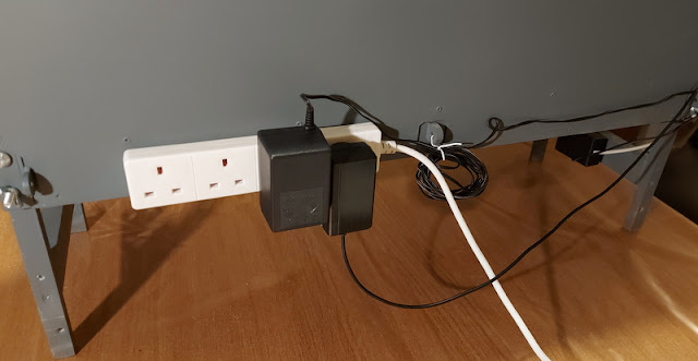
While I was at it I added a couple of screws to the back of a layout for an extension lead to slot on to, this allows the transformers to plug in out of the way. The one on the left is the new layout power, the one on the right is for the LED lighting - the lead for which does not reach the floor. This makes a neater and easier set-up for exhibitions, and less cabling and space needed for set-up at home too. Of course the same power pack will be useful for my other small layouts. 

Sunday, 23 January 2022

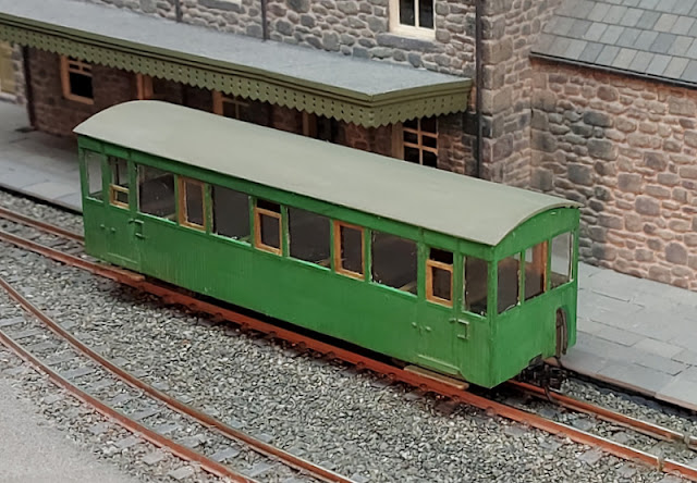
A pane of a job

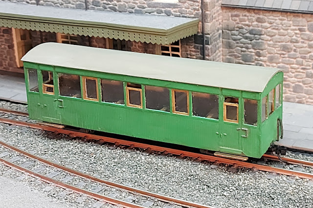
As I am trying to clear a few unfinished projects from the workbench I thought I should finish this Welsh Highland coach, which I'd assembled way back in August 2019. It had actually visited the paint shop soon after, but the job of cutting and fitting the glazing looked tedious, the clear plastic was included in the kit but needed to be cut to fit the recess for each window. It was last summer before I made a start, but it was indeed tedious, progress was slow and the project stalled again until I decided it really deserved to be finished. 

Using my callipers to measure the size and to score onto the clear plastic helped but each pane had to be checked and trimmed several times before it fitted. The recesses allowed just a fraction of a millimetre around each window so poor cutting would result in gaps, or the glazing not fitting flush and flat behind the openings. Each piece was then glued around the edges with Micro Krystal Klear (though my pot is drying up which didn't help) and placed in with tweezers. There are different sizes of windows, and those at the ends have virtually no frame at all, making cutting and fitting difficult. While excess glue is clear and can be removed, the glazing seems to mark easily and unfortunately has gained many visible scuffs and scratches, but at least the job is finally done!


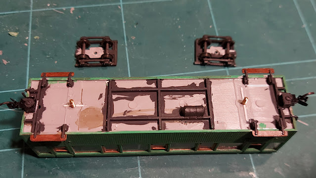
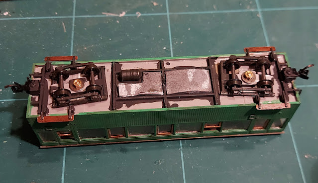
Underneath, the bogies didn't seem to move as freely as I'd like, the contact area being quite large and only allowing rotational movement. The solution is simply a thin strip of plastic either side of the pivot bolt, which reduces the contact area and friction, and allows the bogie to rock slightly. Setting the strip at one end of the coach lengthways and at the other across the coach allows sufficient flexibility in the bogies without allowing the coach to rock from side to side. 


The bogies are fixed to the captive bolts with a nut and washer, but the nut would soon come off with the movement of the bogies. I applied glue to the bolts before adding the nuts, I used the Micro Krystal Klear since it was on the workbench but PVA would do as well, this provides enough hold to retain the nut but it could be removed if force was applied. I also stuck pieces of roofing lead sheet between the frames to add a little weight. 

Finally the roof was fixed with the same glue, which can be prised apart if needed - such as when I get around to fit passengers! At least the glazing doesn't look too bad at normal distances. Although I'd applied subtle weathering when I painted the coach, it doesn't seem to show in these mobile phone photos, though it does look effective to the naked eye. 

Sunday, 16 January 2022

A brake van for the PW train

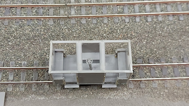
I've been trying to work though a couple of unfinished projects. One is this 009 Society kit for a Royal Naval Ordinance Depot brake van, which I actually started back in the summer while demonstrating at the 009 Society stand at the Amberley rail gala. The body went together easily enough though I took time to make sure the corners went together nicely, the frames at the end of each side are fragile. 


The kit has a nice interior too, with benches and a central brake stand, so the roof has been left off to facilitate painting. However, those delicate sides were clearly going to bow inwards and needed support. The kit sprue provided suitable material to cut a couple of sturdy braces from - cut slightly oversize and filed to be a tight fit. 


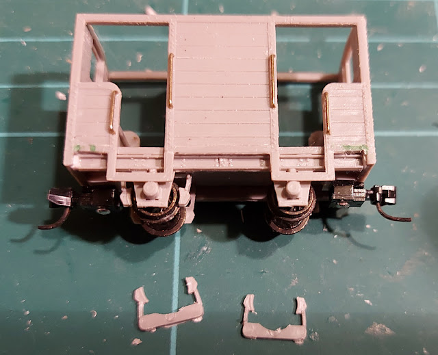
I fitted the handrails after the exhibition, always a slightly fiddly job but they do look good. That was as far as it got for months, but looking to clear the part-finished jobs from the workbench this looked a quick win. So I fitted the underframe and wheels, and added mounting blocks for the couplings. 


The brake blocks proved more challenging. First, with the wheels in place they couldn't be fitted around the wheels - the flanges prevented them sliding in from behind, and there wasn't space to fit them between the wheels and the floor. So I prised the wheels out and stuck them - but once the wheels were back in they didn't rotate! The wheels touched the supporting part of the brake blocks. The solution was to remove the wheels, cut away part of the brake block support plastic to clear the wheel, and refit again. Fortunately, for the second axle I could trim the brake mouldings first! The final job was to fit the steps, left until last as they might have been vulnerable in construction.


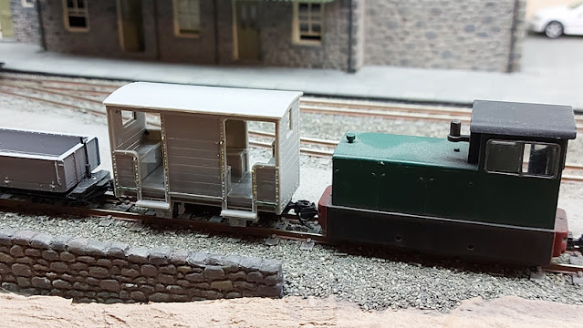
The little brake van will look good as part of the permanent way train on Hexworthy, though the loco looks like it needs dusting. First though, the roof is still loose for painting, the wheels have been removed (again!) as have the couplings, and it is heading for the paint shop. 

Monday, 3 January 2022

Upnor Castle

As an easy post-Christmas project I looked out a 3D printed loco kit I got for my Birthday last year. It is a model of Upnor Castle on the Ffestiniog Railway which was produced by the Merseyside group of the 009 society in memory of Roger Christian, a long-time member of the group who inspired many with not only his modelling skills but his willingness to encourage others, through articles in the 009 News and Railway Modeller, many exhibition appearances, and the 009 Society groups, along with Stan Williams. When I was a young 009 modeller Roger and Stan were a great help and encouragement to me. What a great idea to produce a model in his memory.


The loco is finely detailed and appears to have a good finish, comes with a separate roof and interior, and was supplied with a Kato 109 chassis. This model had a partially broken and distorted cab step, Stan had warned me before dispatch. There are no instructions, but clearly the Kato chassis would need shortening to fit the body. 


I cut of the balconies leaving the chassis much shorter than the body, it fitted neatly in but I felt the body sat too high. I cut off the clips and a strip from the "shoulder" of the chassis alongside the motor which allowed it to sit much lower, but the chassis rocked fore and aft. I added strips of 40-thou plastic to the flats at the corners of the chassis allowing it to sit level. Finally, plastic end-stops added in the corners of the loco frames stop the chassis moving fore and aft within the body. The chassis is held loosely vertically in the body, though it doesn't fall out I may use blue-tack or a spot of glue to hold it in place when finished. 


The next job is fitting couplings. Opening up the buffer-beams for the Microtrains couplings was easiest with a saw, since the 3D printed resin is sawn and files cleanly but isn't easy to cut with a knife. I passed a fretsaw blade through the slot and opened out the hole, then cleaned up with a file. I drilled a hole for the retaining screw, and made a recess in the bottom of the buffer-beam for the screw head. 

I spent some time checking the body and cleaning up blemishes, which I guess are from the support structure during printing, and were mainly on the bottom of the frames and footplate, and around the window openings. The deformed step was easily superglued back together, and I glued plastic strips across the back of the cab handle recesses which were open into the cab. I also thinned the back of the cab back where it meets the roof, and the back of the protrusion below the cab roof, as it initially sat a little forward with no overhang to the rear. 


Now I need to get some primer to continue, the first coat will show how smooth the surface is though it appears pretty good.