Showing posts with label power pack. Show all posts

Monday, 11 September 2023

No crossed wires

As noted, the wall-wart 16V AC transformers have a very similar plug to the 12V DC power supplies used for the LED lighting. Clearly plugging in the wrong power supply could be bad (for the lights), so clear labelling is needed. 


I already colour code my controller (5-pin DIN) plugs red, and the power-box leads (6-pin DIN) blue. As previously explained, Slugworth can now run either from the power-box with the controller plugged into that, and the blue 6-pin DIN plugged into the layout, or with the controller plugged into the layout and a 16V AC supply connected. Here the 6-pin socket is coded blue (no AC) or red (with AC), with the controller plug (red) in place, and the 16V plug and socket coded yellow and labelled AC. 


The LED lighting plug and socket on the other hand is coded green and labelled DC. No confusion there. 


The AC supply into the "mini power-pack" for Loctern Quay is also coded yellow, the transformers being interchangable between layouts. 


And the Loctern Quay lighting supply is coded green. Simples!

Tuesday, 5 September 2023

Rethinking power supplies - Slugworth simplification

A while back I discovered that a simple Hornby "wall-wart" transformer could be used to power my layouts, a much neater and more compact solution than an open-frame transformer mounted in a home-made power box (see below). So I thought it worth getting another. This one is a Hornby C912 rather than the C990, it's rated 16V AC at 14VA which I make to be 875mA, so pretty much the same as the C990 which is rated 800 mA at 16V AC. Either type can be bought on ebay for less than £10. 

When I made the "micro" power pack I'd just hard-wired the power lead in, but it seemed neater to fit a plug and socket, and allow the transformer to be interchangable - not least as I like to have a spare at exhibitions. The transformer comes with a 2.5mm (inner) x 5.5mm (outer diameter) power connector, so I used a matching socket from Squires, and refitted a matching plug to the existing transformer. 

Now the folllowing gets a bit involved! There is a risk with these connectors in that the LED layout lighting uses the same/similar type for 12V DC. In fact, the 12V transformers seem to use 2.1x5.5 plugs which strangely fit 2.5x5.5 sockets, very confusing. I think if I adopt 2.1x5.5 sockets for the lighting they will still work with the 12V DC lighting supplies, but while the AC supply 2.5x5.5 plug will fit the socket the inner contact will not be made. This all seems a bit odd! In any case, some clear labelling may be needed. 

The convenience of the wall-wart transfromers has made me rethink my power box strategy. The original design provided not just 16V AC to both controller and layout, and so 12V DC from the controller, but also a high-frequency track cleaner, and a capacitor discharge unit (CDU) for points, all fed to the layout via a 6-pin DIN plug. The idea was that it kept all the complex and relatively expensive components together in a box that can power any of my layouts, rather than having to add them to each layout. 


Now, I no longer use a high-frequency track cleaner, modern motors don't like them and anyway the use of graphite on the rails has made them redundant. I've also found that the points on a small layout can be driven via a simple CDU made of 3 components in a choc-block connector, as provided in the mini power box seen above. However, some layouts - such as Slugworth - use manual points control and don't even need the CDU, so the mini power box is now simply a junction box. Clearly, it can be eliminated altogether...

So Slugworth has been modified by the addition of a 16V AC input socket for the transformer. This is wired into the 6-pin DIN socket. Now a 5-pin DIN controller plug will fit a 6-pin DIN socket, and fortuitously when I first wired my power box leads I matched the controller 12V DC and 16V AC pins between the 5 and 6 pin connectors (although for the controller the 16V flows in, from the power box it flows out). So here the controller can plug into the 6-pin socket and both it and the auxilliary 16V AC supply (e.g. for lighting) are powered from the plug-in wall-wart transformer, with no external junction or power pack needed. 

Of course, as the existing wiring is unchanged the power box can still be used with the controller plugged into that, and no separate transformer is plugged into the layout. This seems a bit complex but hopefully the diagram makes sense.

I did add a thermal trip to the 16V AC supply, I expect these sealed transformers have one built in but better safe than sorry. This trips at 1.6A which may be a bit high, but if there is a short it should trip. 


This view underside of Slugworth shows the existing socket (left) with the controller plugged in, and on the right the new power socket for the 16V AC transformer wired to both the controller socket and to the lighting power circuitry. Of course this is how many people already wire up their layouts, but the approach I've used maintains "backward compatibility" for the existing power box to be used instead, or as a back-up. 

This simple modification could be made to any of my smaller layouts to eliminate the need for a separate power box (and another lead), and just use a cheap wall-wart transformer. Layouts that need a CDU for point control could have the simple circuit added on-board too, although for now the micro power box used on Loctern Quay does that job. 

Tuesday, 1 February 2022

Micro Power Pack

My layouts are all powered the same way: a hand-held controller plugs into a power-box, with a lead to the layout providing power for points and accessories as well as the controller output. I've got two power boxes, one is quite large and heavy and supports two controllers (though none of my current layouts need two controllers!) and the second is smaller for one controller. However, even that is quite bulky and designed to sit on the floor, and I end up taking both to shows so I have a spare. Last September I used an old Hornby transformer (from a simple train set controller, which broke) to rig up a temporary back-up supply, since this seemed to work OK I figured I could make it into a more compact and tidy solution for my small layouts - let's call it the micro power pack. 


I got a small project box into which the controller plugs, with a lead to the layout, and taking power from the transformer. The box needed to include a capacitor discharge unit (CDU), I used the same simple circuit I'd used on my smaller power box which uses a diode, 2200uF capacitor, and a resistor. The resistor limits the "charging" current flow; this transformer is only rated at 800mA, but gave out about 18V AC which is about 24V peak, so I reckoned a 33 Ohm resistor would do (V=IR and all that). Of course, I didn't have a 33 Ohm, but twisting a 47 Ohm and 100 Ohm together in parallel gave (according to my multi-meter) about 33 Ohms. That simple circuit aside, the box simply acts as a junction box for the AC and to pass through the controller DC. 


So I measured how much space the terminal block needed and ordered the box, and a capacitor. Then I figured I should put in a thermal cut-off to protect the transformer from a short-circuit. Of course, the capacitor was larger than I'd allowed for, and the cut-off needed another terminal... resulting in an enjoyable (?) puzzle to figure out how to fit it all in. This life-size drawing around components helped me plan. I also wrote out which colour wires go where, as I am easily confused mid-way through soldering.


To drill the box for the socket and holes for the wires I used an offcut of timber to support it. The DIN socket needed a 15mm hole, and I found a couple of small self-tapping screws to hold it in place, the thicker cable needed a 5.5mm hole and the thinner cable to the transformer a 3.5mm hole.


The worst job is wiring the 6-pin DIN plug, the pins have tiny recesses into which the wires must be soldered. Remember to slide the plastic cover up the lead first. At least the sockets have tags.  


Everything fitted in, but it is a snug fit! At least I didn't need to worry about securing the connector blocks, as nothing can move. Note the cable tie securing the white cable to prevent it pulling loose, the black cable from the transformer is simply knotted. I checked all the connections and tested it, I'm pleased to say it works just fine. Points can be changed one at a time at about 1 second intervals, any faster and the capacitor doesn't have time to charge, but that's fine for a single operator layout. Surprisingly, a loco continues to run smoothly while points are changed, given the single 800mA transformer powers both I'd wondered if this would be the case, although on small shunting layouts I tend to change points only when stopped. 

The same arrangement could be used with any separate 16V AC transformer, including the accessory output of a cased controller. It would be easier if the box were bigger, in fact a larger box could take a "proper" CDU capable of powering multiple points if needed. The advantage of this arrangement is that there is one plug to run the layout (though I keep lighting power separate), the transformers and CDU can be used on multiple layouts, and mains wiring is kept well away from the layout itself.

Note that because the points and controller share a transformer winding here they should not share the same common return on the layout, nor should any accessories powered from the 16V AC. 


The box had Velcro stuck to its base, and with some Velcro stuck on the legs of Loctern Quay it can be neatly fixed out of the way, with the short power lead connected to the layout. 

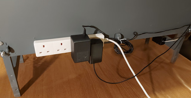
While I was at it I added a couple of screws to the back of a layout for an extension lead to slot on to, this allows the transformers to plug in out of the way. The one on the left is the new layout power, the one on the right is for the LED lighting - the lead for which does not reach the floor. This makes a neater and easier set-up for exhibitions, and less cabling and space needed for set-up at home too. Of course the same power pack will be useful for my other small layouts. 

Tuesday, 28 September 2021

Returning to exhibiting

Big exhibitions are back. It's been a while, but since restrictions lifted over the summer there have been a few exhibitions. It was a bit of a surprise to be invited to a big show - The Great Electric Train show in Milton Keynes (2nd and 3rd October) - and with not one, but two layouts. I will be taking Loctern Quay, and my Son Joshua will bring his Slugworth & Co. layout too. 

The thought of exhibiting again brought realisation that some jobs needed doing. We've dusted and tested both layouts and their stock, although no need to clean track the graphite on the rails was touched up. A while ago Joshua bought a new loco at the 009 Society sales stand - this rather nice Lilliput 0-6-0 - which ran nicely but looked rather plasticky. Clearly it needed to look more realistic, but we had little time, so a touch-up and weathering was in order. I forgot to take a photo beforehand, but here's how it ended up:

In the end I painted the smokebox, chimney, roof, and footplate matt black (the boiler staying black plastic), the buffer beams in red (the front was black, the rear green), and dry-brushed some brass onto some of the pipes and fittings on the boiler. The valve gear was dry-brushed a mix of gunmetal and silver, with some graphite rubbed onto the moving parts. The whole loco (except moving parts) then got a very thin wash of dirty brown to dull down the plastic and add some relief as well as a hint of grime, followed by a dusting of brown weathering powders on the lower parts and black on the roof and boiler top. This didn't take very long, but has made a massive difference. 

My Minitrains Decauville was treated to the same weathering treatment. Further detailing may follow, but like the Lilliput it was mostly self-coloured plastic, and the toning down and extra relief from the weathering adds a lot of realism. 

The Decauville has a Microtrains coupling fitted to the rear, but I'd still not got around to changing the front coupling as it looked tricky. This is quite useful, as it can operate on Loctern Quay and Slugworth - since on both layouts locos only need a coupling on one end. The Lilliput is a touch large for Slugworth - the cab barely clears the scenery on the corners, and the rear overhang is rather large - but we found some stock it will pull coupled to the front. I also changed couplings on a couple of small coaches I found for Joshua to run, from one of my early layouts. 

As well as having spare locos I like to have spare controllers and power supplies for exhibitions, though I don't think I have ever had one fail. I have plenty of controllers, although one I'd picked up a year or so back still needed a plug fitting. I also have two power supply packs, but of course we will have two layouts, so a third could be useful. Slugworth & Co. only needs a controller input and a 16V supply for the lights, these are provided through a DIN plug, but with no point motors no CDU is required. I found an old Hornby 16V AC "wall-wart" transformer from Joshua's first train set, the rather nasty controller had failed but you never know when a transformer will come in useful!

It's not pretty but it works! The controller plugs in the DIN socket at the top (with the red marker), taking its 16V AC input from the transformer. The DIN plug at the bottom (with the blue marker) plugs into the layout, providing the controller input, and 16V AC for the lights (the same supply that drives the controller will be able to manage the lights too, it is rated 800mA). It's actually quite a handy compact power supply for my micro-layouts that don't have point motors. Sometime I can mount the terminal block into a suitable box rather than clingfilm, but time is tight and it works!

So all is ready for the show, if you are there do say hi!

Monday, 4 November 2019

Mini Capacitor Discharge Unit

As I mentioned in the last post, I took my part-built 009 society challenge layout to show on the demo stand at EXPO-NG. This layout has solenoid point motors, and I recently posted about my large power-pack, now fitted with two transformers (for two controllers) and a big capacitor discharge unit (CDU) which will power up to 6 points at once. I also have a mini power-pack with a single transformer, much more suitable for micro layouts, but without a CDU it couldn't power the point motors on the challenge layout. I didn't really want to take the larger, heavier power-pack, so could I fit a CDU inside?

I had a vague idea what was needed, but a quick google turned up a useful site that confirmed the circuit diagram. Essentially a diode creates a DC supply from the 16 V AC input, a capacitor stores energy to kick the point motor over when required, and a resistor prevents the solenoids burning out if a switch is left "on" by limiting current flow. My sketch of the diagram is shown below, along with my implementation using a choc-block screw terminal.


What's more I found a diode, a 2200 uF capacitor, and a pack of resistors all in stock, so I gave it a go. The completed home-made CDU is shown below, about to be squeezed into the box. I didn't know where to start with the resistor, so put in a 1 kohm, it worked but took >30 seconds to recharge before it would work again - not ideal! I went down to 100 ohms which was better, but then I thought I could do some maths. I measured the voltage at the capacitor - about 22 V - and reckoned up to 1 A should be safe for the coil, at least for a few seconds. V=IR means a resistor of 22 ohm is the smallest I should use, so I found one and fitted that. The recharge time is now under a second, so perfectly adequate for a layout with just three points.


So the mini power-pack not only provides a single controller from one winding of the transformer, but the other winding now powers the track cleaner, the CDU (22 V DC pulsed), and a 16 V AC supply for any other accessories. The 5-pin DIN socket is for the controller, and the 6-pin DIN socket takes track power, CDU, and 16 V AC to the layout. Also seen in the box is a switch to power on/off the track cleaner, and a thermal cut-out protecting each of the transformer windings.


The track cleaner is rarely used so I could remove it, which would provide space for a "proper" CDU (larger, faster recharging, better point motor protection). However I'm happy with the way the simple CDU works for one point at a time, and with an acceptable recharge time, at least for small layouts.

Tuesday, 15 October 2019

Upgraded powerpack

I have two "power-pack" boxes for my layouts, a large one and a small one, and when I take a layout to an exhibition I take both in case of failure - though it hasn't happened yet! However with two layouts going to Uckfield I wouldn't have a spare. The large box was always intended to hold a second transformer, but I had never needed to fit one - well now seemed a good time.


Inside you can see the original transformer on the right - made by AMR it has two 16 V AC and a 24 V AC output, the latter is used for the capacitor discharge unit (CDU) for point motors seen at the rear. One of the 16 V AC outputs is used for a hand-held controller which plugs into the box, the other provides power to accessories and also the high-frequency track cleaner seen in the foreground. The new transformer is fitted rear left, it's a Gaugemaster T1 with two 16 V AC outputs allowing a second controller to be powered. Note the circuit breakers directly fitted to the outputs. The track cleaner has two outputs and could be wired into the second controller, but since adopting graphite it is rarely used so I haven't bothered.

So two controllers can be plugged into the box by 5-pin DIN plugs, and two 6-way DIN outputs each provide the controller output, 16 V AC for accessories, and the CDU output for point motors. Some years ago I posted the schematic below:


The new transformer effectively duplicates this circuit with a second transformer, controller, and output, except that there is still only one CDU feeding both outputs, and I've not bothered to wire the track cleaner to the second controller. It can thus power two layouts, or one layout needing two controllers.


Here are both power-pack boxes together. I made up a new 6-way lead to connect to the layout, my spare was made from single-core telephone wire and I'm amazed it hasn't broken already - so now I have 3 leads. I've also adopted a colour code to make plugging in quicker and easier - blue is the layout connection, red is the controller, tape on the cables and sharpie pen on the sockets.

The small box contains a single transformer (2 x 16 V AC) and a high-frequency track cleaner, providing a single controller and accessory supply in a small package ideal for micro layouts. Until now my small layouts have mostly had manual point control so there is no CDU, but I'm thinking of adding one if it will fit, or removing the rarely used track cleaner to make space.


As well as the new transformer I have a new controller, a Gaugemaster W. Unlike most of my other controllers this is not a feedback type or pulsed output controller, but simply a smoothed DC output, and so is ideal for coreless motors which are becoming more common. Initial tests show it doesn't have good slow speed control - at least of conventional motors - which I expected, but also it didn't maintain a steady speed, so it doesn't seem as good as my other controllers. However it may be better with coreless motors and safer for continuous running.


As you can see I now have quite a collection of controllers. As well as providing a choice of controller type depending on layout and loco type, it means I can always have a spare available for a show. This proved useful at the last Wealden group show when a broken wire caused issues, easily fixed but not something you want to address at the show!

Tuesday, 19 May 2009

Layout Powerpack

There has been some discussion on the NGRM forum recently about controllers people use. Since I don't have a lot of time for modelling at the moment, I thought it would make an interesting post to describe the powerpack and controllers I use.


I claim no originality for this idea - I got it from a book by Cyril Freezer, and I'm sure it is widely done - but I liked the idea of the main components of the electrics being in a separate box. This keeps all mains wiring in a box on the floor, and also most attractively, allows the expensive bits to be used for many layouts! I made this one with my Dad years ago, when my trainsets evolved into model railways, so I reckon it has powered 8 layouts now ...


Anyway the basic principle is to provide the layout with all the power sources it needs, in this case a controlled 12V DC for the track, a pulsed 20V DC for points (i.e. a CDU), and a 16V AC supply for anything else - though so far I haven't found anything that needs it! My powerpack contains a transformer with 2 x 16 V AC outputs, both protected with thermal circuit breakers (this is very neccessary to avoid blowing the transformer in the event of a short-circuit), a Capacitor Discharge Unit for points (can't recall the make), and a high-frequency track cleaner (Gaugemaster). The latter can be switched out, in case of delicate motors! The schematic below should make all this clear.


All this is contained in a sturdy wooden box, the mains cable is clamped, fused at plug, with a neon to show the power is on, and of course the transformer is earthed. Some vent holes, a handle, and a couple of hooks to provide somewhere to wind up the cable complete it. There are two DIN sockets, a 5-way is the standard for hand-held controllers (16 V AC in, controlled 12 V DC out), and a 6-way for the lead to the layout. Each layout then just needs a socket for power in. See photo below.


In fact I have a second powerpack, an ultra-small one for very small layouts (one of my layouts is not much bigger than this powerpack!) containing just a transformer and track-cleaner. Points need to be manual, or as on Southon Yard, I built a simple CDU into the control panel for the single point with a rectifier and capacitor! If you wanted to avoid doing mains wiring, you could mount a cased transformer onto a board or in a box containing the low-voltage wiring.


The photo also shows the hand-held controller, in this case an AMR. They are long since out of business I believe, but I picked up a second one second-hand recently. I also have a Gaugemaster "HH" which is very similar, but I prefer the toggle direction switch of the AMR to the slide switch of the HH - it is kinder to the thumb! I also think the AMR gives better control, but I have no way of measuring it! Both are of the "feedback" type which I find gives good low-speed control. I don't run loco's far or for long on my layouts, so I have never seen any overheating issues that some find with feedback controllers and HF track cleaners.

Posted by Picasa