Tuesday 17 July 2018

Amberley rail gala 2018

Last Saturday I was at Amberley, where they were having the annual railway gala weekend. This year the event celebrated the 100th Birthday of Peter, the Bagnal 0-4-0ST.

IMG_5124

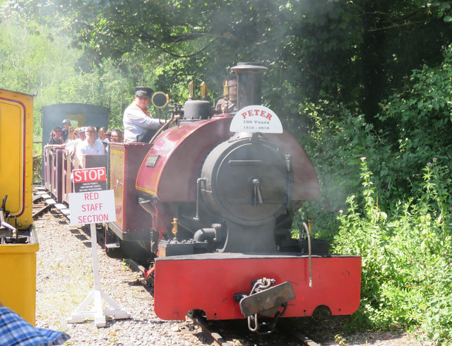
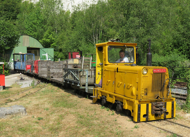
The format of the event was similar to previous years, with two passenger trains running, interspersed with demonstration goods trains and light engine movements, so there was always something interesting happening.

IMG_5094

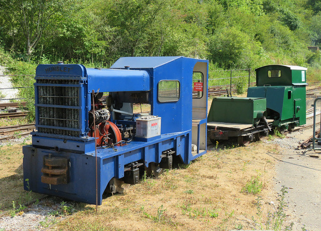
It was nice to see a line-up of three ex-Thakeham locos, although they were not running.

IMG_5091

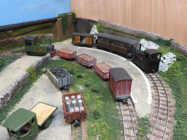
Inside the shed was the model railway exhibition - smaller than it has been some years, but still plenty to see. Richard Glover had brought his new micro layout Brockles Ghyll in 009.

IMG_5080

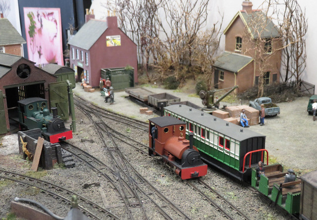
John Wilkes was showing his layout Coleford, the subject of several magazine articles and now the feature of a book published by Narrow Planet. John manages a different perspective which makes the layout interesting and different. Just look at that track-work, and the winter trees.

IMG_5140

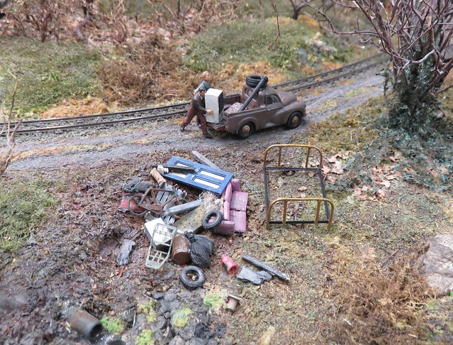
The cameo scenes on the layout certainly avoid the usual cliches. Like this fly-tipping scene!

IMG_5108

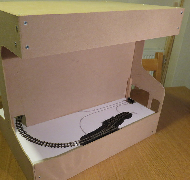
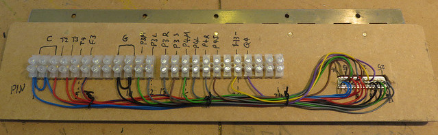
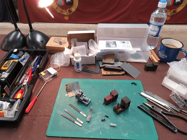
I was there helping to man the 009 Society stand with the Sussex Downs 009 group. Our usual approach is to run a demonstration stand alongside the display case and our small demo layout, which often gets people interested in what we're doing and the scale in general. Here's my work-space.

IMG_5150

I'll soon post an update about the projects you can see... in the meantime, more pictures of the event can be seen here.

Wednesday 11 July 2018

A board becomes a layout

The next step with the baseboard was to add fascia panels to protect the foam-core board, which although surprisingly strong is not very robust. Joshua also wanted a back-scene and a lighting pelmet, for such a small layout it made sense to make them integral. The whole lot was cut from a sheet of 3mm MDF; the end pieces forming a support for the backscene and lighting, with a "lid" on top to cover the lighting. The front, rear, and end pieces were glued to the foarm-core board and also screwed to the blocks that had been set in the corners. Small strips of wood were used to help join the backscene to the ends, and blocks behind the lighting pelmet joined the top pieces together.

IMG_4369

As you can see at this point track-laying had already started, as we'd realised it would be easier to lay the curve through the backscene and the point control wires before the backscene was in place. The curve is pretty tight, so the rails were slid out of the sleepers and pre-bent between fingers, before re-threading the sleepers back on. Track is glued down with PVA, held with a few track pins pushed into the foam-core until the glue has dried.

IMG_4372

Point operation is by wire-in-tube, which was laid into a groove cut into the top of the foam-core board and held with hot glue. We've used the simple but effective trick of connecting the wire to a slide switch, which deals with frog polarity.

Monday 9 July 2018

Another distraction

In my last post I referred to a couple of distractions from my usual modelling plans, this is the second one.

Having helped me with exhibiting my layouts for the last few years, my son has been saying for a while that he wanted to build his own 009 layout that could be taken to exhibitions, a small layout like the EXPO challenges. Then he found out about the Dave Brewer challenge for this year's EXPO-NG show, which is to build a layout 50cm by 35cm, and decided that he was going to build a layout to enter.

Of course what that means is that he is going to get me to help him build the layout, including advice and doing anything he deems too tricky, so the result will be a bit of a joint effort. However that does leave us a challenge in simply making the time to work on it - there's not a lot that Joshua could do without supervision, and I'm not doing anything without him.

2018-01-17 20.10.24

We've been working on it for a few months now, but I'll rewind the story to the planning stage. This was mostly done full-size on a piece of lining paper, with paper point templates, and some mock-up buildings made from cereal packets. We tried out a few ideas, and even has some input from Mum, before he settled on the design he wanted.

IMG_4349

The baseboard was made from foam-core board, which is easy to cut with a knife, even for an 11 year old. The parts are stuck together with a hot glue gun. The top is double thickness, laminated with PVA glue, and blocks of wood were set into the corners ready to screw side panels to later.

IMG_4348

More soon...

Sunday 1 July 2018

Another Control Panel

If you've noticed that updates on my modelling activities have been limited of late, there are a couple of distractions that could explain things, and not just holidays and the hot weather.

The Sussex Downs 009 group are building a new layout, and I seem to have got the job of wiring it up, possibly because no one else seemed to want to. After some time thinking and planning I have adopted my usual approach of coding the wires, and using lots of terminal blocks, hopefully making it easier to follow - and debug in future. However, it became apparent that progress during fortnightly meetings was rather slow, so I brought home the control panel for some homework.

IMG_5064

I can take no credit for the box itself as that is the work of Martin Collins, who has much better woodwork skills than I. The panel is my usual approach of a sheet of aluminium, with a computer printout schematic diagram, and a layer of clear plasticard on top. The coloured switches operate the track sections while the silver ones operate the points. The two grey cables run one to each of the two baseboards.

IMG_5067

Inside (the panel is upside-down in front of it's box) may look messy, but the terminal blocks are labelled according to wire codes, and simply link the switches to the track, point motor, or appropriate power supply, so should not be too hard to follow. The incoming power connections have yet to be made, and the big cables need some kind of cable grip.

IMG_5065

The multi-way connectors weren't much fun to wire up but I've not found a better alternative for this many pins, that isn't too bulky or costly. Each connects to a hinged panel on the back of the baseboard, one of which is seen here.

IMG_5066

The back of the panel has more terminal blocks - which connect from the socket to the various parts of the layout. The seemingly random letters and numbers are the codes for each wire, the wires are colour coded according to purpose too. This panel will hinge down for easy access if required.