Monday 22 May 2017

Latching Fiddle Yard Mechanism - A Prototype

The Sussex Downs 009 group are building a new layout, and discussion at the last meeting came to how we'd build the fiddle yards. The design calls for two turn-tables each with 4 tracks, that are able to quickly change between trains and turn them without handling. This is far from a new idea, the traditional design uses a sliding bolt (as seen on doors and gates) to provide both mechanical alignment and electrical contact to each track. A simple idea that works well enough, but in the smaller scales, the need for precise alignment conflicts with the need for the bolt to slide and engage easily, which can mean they can be stiff or fiddly to use.

I saw an idea posted on a forum some time back that used a pivoted lever with a notch that engaged on metal edges aligned with and underneath the tracks, all that was needed was to depress the lever to release the engagement and move the deck until the next one engaged. The problem was it was bulky and required a lot of space below the deck, which the club layout design didn't allow. I felt the concept was sound though, and after some thought I came up with way that a similar idea could work in much less space, and be constructed with minimal need for accuracy and without special tools or skills.

Ideas are all well and good, but the only way to be sure it works in practice is to try it out. So I raided the garage for leftover bits of wood and PVC foam-board, and with literally no expense spared incurred, built a mock-up over a couple of spare hours at the weekend. The size was dictated by the materials to hand - the deck is about 18" long and 9" wide, long enough to demonstrate it - while construction is somewhat crude. I've added other ideas too like the handle/gate. Now, let me show you the idea...

1_Overview_

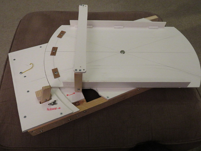
An over-view with the deck turned to the front track. On the deck are three pieces of PCB to which tracks would be attached, and through them the top of a brass tube/pin protrudes and is soldered. The handle we’ll come to later. To the left is the release mechanism – push the wooden lever to the left to unlock the deck to turn. The lever was an afterthought "improvement" - initially I just pushed the wing-nut (which could have been a nice wooden knob) to the right, but the lever is nicer to use. I guess that's the point of the mock-up!

2_LockingMechanism_Top

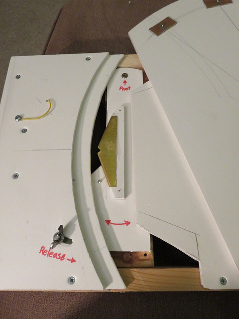
Under the deck you can see a brass “latch” (triangular with a notch at the top) attached to a pivoted lever, the free end of which is moved by the release knob (bolt) - and now the lever too (fitted after I took this photo). The support for the deck is shaped for a particular reason.

3_Underside

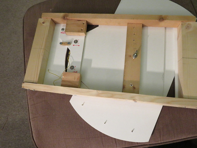
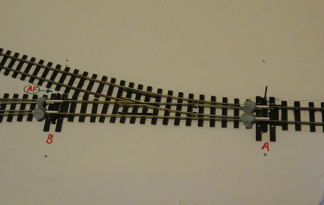
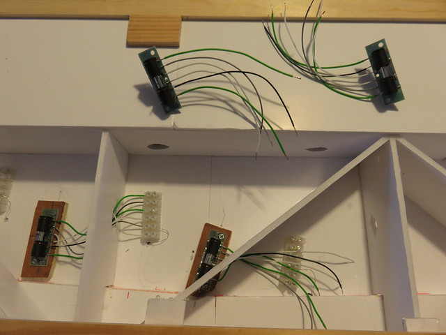
From underneath you can see the three location pins (brass tubes) protruding down through the deck, and the latch arm locking mechanism which pivots on the lower wooden block, the other end slides on the upper wooden block.

4_LockingMech_Below

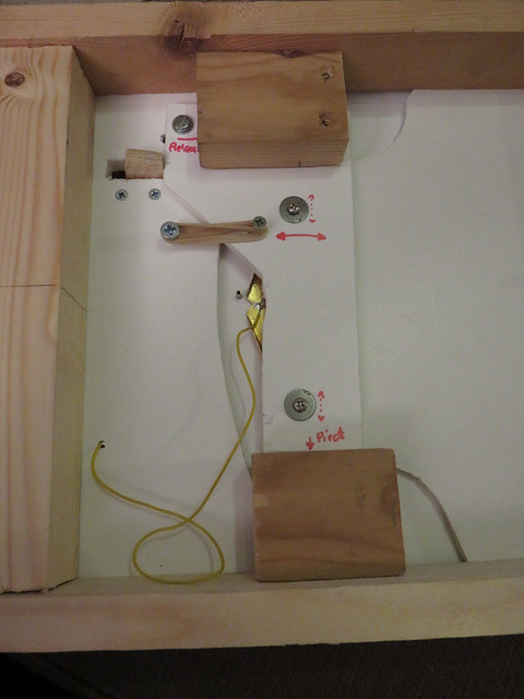
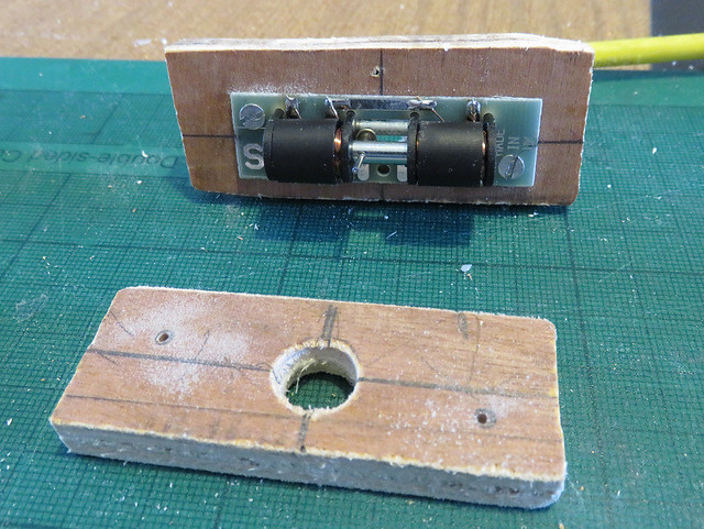
The latch arm close up, the bottom is the pivot, the top rotates as per the arrows, and is pushed by the bottom of the wooden lever. The high-tech tension device (rubber band in this mock-up, but a spring would be better!) pulls on back the latch arm. The bass latch can be seen with a wire from it, and against one of the slopes a location pin can be seen from the deck. As the deck is rotated this slides up the brass latch by pushing against the lever until it drops into the vee shaped notch, holding it securely and making electrical contact between the brass latch and the PCB above.

5_SideView

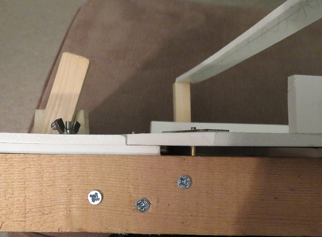
The location pins only protrude about 5 mm below the deck so clear the frame of the board – the foamboard is 5 mm thick - and at the top, protrude just far enough to be soldered to the PCB, and not foul locos passing over them. The rest of the mechanism is contained within the frame. This makes it reasonably straightforward to build this mechanism, and contain it within a conventional design and depth of baseboard.

7_HandleFoldedToRotate

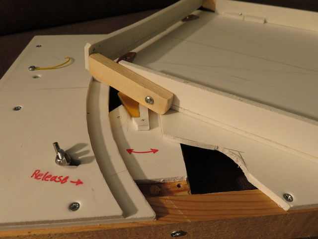
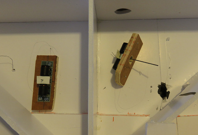
Back to the handle. In the up position the tracks are clear, but when pushed right over the bottom of the handle uprights contact the supporting board below stopping excess movement. With the handle folded down the deck is free to rotate beyond the last track – i.e. can turn right around - as seen here.

Operation is simple: simply push the lever  to disengage the pin and rotate the deck, once the lever is released the deck latches at the next track that it aligns with. As the brass pins are round, and the notch is vee shaped (with rounded entry), alignment is actually very precise - as the pin reliably self-centres in the vee. No effort is required by the user to achieve this, the deck is simply rotated until the pin clicks into place. Electrical contact is also made connecting the aligned PCB (i.e. table track) to the fixed track.

This system would be just as useful on a traverser or sector plate as a turn-table, and had I thought of it a couple of years back, I'd have used it on my "exhibition" fiddle yard for Awngate instead of the micro-switches. Some of the construction details could be improved from my quick mock-up, but overall I'm happy to say the concept works well.

Wednesday 10 May 2017

Decoding the Wiring Enigma

I don't do a wiring diagram, but I do plan out the wiring before I start. The key is the track plan, with track feeds marked, and a "code" given to each feed, point, and indeed each wire. The wires are connected from switches to track and point motors, via terminal blocks, following the codes to label each wire.

Hexworthy has just four points, I've labelled A to D. Each has a feed to it's frog (in this case, the wire dropper from the PECO points) which is switched by the point motor, and I've labelled them Af, Bf, etc. There are 5 switched track sections labelled 1-5, I put the feed into the rear rail (as the wire is less visible) and only gap that rail, so fewer "common return" feeds (labelled R) are required. Because of the live frog points breaks are required in both rails of both joins between the red and green sections.

HexworthyWiring

The switch wiring schedule is pretty straightforward, the table above shows the wire codes for the input and output of each switch. "T" is the controller track output, and "P" is the point motor power from the capacitor discharge unit (CDU). Note that the sections may be fed from the adjacent track, so for example section 5 is only live if section 4 is switched on and point C is set to the siding, as well as switch 5 being on.

Wiring to and from the switches is via screw terminal blocks that make the wiring easier to follow, make joining wires easier, and providing a point to de-bug if needed. There are terminal blocks for the incoming power supplies (from a 6-pin DIN socket), the connections to the panel, and as shown previously - one for each point motor which includes the frog switching as well as the motor connections. From the track plan it can be seen which rails are being switched, so the inputs come from the section, return, or previous frog feed - this saves extra wires to the rails. Example terminal block connections are shown above, the colours indicate the wire colour used.

IMG_2990

This is the result with all the wiring in place - surprisingly complex for such a simple track plan! At the top of the picture the control panel is lifted out to access the switches at the rear, below it the terminal block feeding the switches can be seen. On the right are the connections to the power socket, note that the return wires are linked over two terminals to make room for multiple connections. Below and left can be seen two of the point motor connections. All terminals are labelled with the wire code denoting the connection to switch, point motor, or track, so wiring up is simply joining the dots.

IMG_2991

The other end of the board is a little less busy. All that remains is to tidy the cables, bundling together with tie wraps or a twist of wire, and securing where necessary.

You can see I've cut a slot in the foam-core, that's a hand-hole. I was finding it difficult to find places to grip when moving the layout around!

IMG_2989

Up top the markings for the feed wires can be seen - and if you look closely, the wires can be seen soldered to the rails. I feed the wire through a hole in the board and form the end into a "7" shape, tin the end, and hold it against the rail web while pressing a soldering iron against it until the solder flows - hopefully giving a neat and secure join.

The loco is on a test run. I'm pleased to report it all worked first time! The careful planning has paid off.

Monday 8 May 2017

Panel Games

Before wiring can commence I needed to finish the control panel, which had been mounted into the front fascia of the baseboard. The schematic is laid out on the computer - I use Word, which has simple drawing tools that allows objects to be drawn to a measured size so the printed size is known. The drawing is duplicated, one has the switches drawn in place - ensuring there is space between them, and marking the centres. This print-out is stuck on the aluminium panel, and the centres of the switches punched.

IMG_2940

I then took the panel into work and used a pillar drill for the switch holes, and not forgetting the screw holes in each corner. These took a bit of cleaning up with various files.

IMG_2941

On the back of the panel I also drilled a small hole part-way through above each hole, this is to locate the tab on the keyed washer that stops the switch from rotating. The second print-out (without the switches drawn on) is cut to fit, including switch holes, as is a piece of clear plastic. I used a piece of packaging, but anything clear, stiff, and about 10 thou thick will do. The switches are mounted through the three layers.

IMG_2942

With the panel screwed in place the result is a neat, easy to follow panel for surprisingly little effort. Recessing the panel means the edge of the plastic and paper layers aren't seen or vulnerable. I've added coloured rubber grips to the section switches to match the diagram, while point motor switches are left silver.

IMG_2992

Wednesday 3 May 2017

Fitting Point Motors

I gave some thought as to which point motors to use. Slow-acting motors have become popular, and we're using Tortoise motors on the latest club layout, which seem well designed and made. However they are very deep, and even the 3.5" depth of the Hexworthy base-board is insufficient, so they don't suit shelf layouts. They are also pricey, and I've heard mixed reviews of cheaper versions, even though I only need four I find it tricky to justify £10-20 per point. The thing is, I don't really see the need for slow acting motors - whenever I've seen a real point move it's with a "clang" that takes less than a second. OK, so solenoids go faster and with a "Thunk", is that worse than a 2-3 second "whrrrrrr"? It's never bothered me...

Servos have started to become popular in recent years. They are cheap, but need a mounting arrangement, and a circuit to drive them - while there are various options for this (including from PECO) they do push the cost up and they aren't simple. I've also heard reports of them "jittering" or moving due to voltage spikes or noise from motors.

Solenoids are relatively cheap, reliable, and simple. My choice are SEEP motors, they are easy to fit under the baseboard with no extra fittings, and have the necessary built in switch for frog polarity switching. Those on Awngate were salvaged from a previous layout and so are probably over 20 years old, I admit they're not used intensively but I've only ever had one failure - and that was repaired. I already have the Capacitor Discharge Unit (CDU) in my power-pack to drive them, and a simple passing contact switch or push button is all that's needed to operate them.

The one problem I have had is that the motor requires enough movement to switch the switch properly, but on Awngate with a 6mm baseboard the movement of the 009 point tie-bar was barely enough, requiring some careful set-up. It struck me that the motor can travel further than the tie bar as the pin invariably flexes a little, so if the motor was further from the point the excess movement could be increased, and the need to site the motor perfectly would be reduced.

IMG_2811

Firstly a ruler was set along the tie-bar and a pin pushed through the foam an inch or two from either end. Underneath the board the pin holes were joined with a pencil line marking the line of the tie-bar, the point motor should align with this to work effectively. Next the hole for the actuator pin was opened up from below with a scalpel, wider at the underside than above, ensuring the pin cannot foul on the foam-core (which is double-thickness, so 10mm deep here) even if the motor travels further than the point tie-bar. The hole was later painted black. Note the wire in the centre of the picture, which is the dropper from the point crossing vee/frog.

IMG_2810

Previously I've glued the SEEP point motor base directly to the underside of the baseboard. I figured it would make them easier to change in the event of a failure if they were screwed in place, so I made some mounts from 9 mm ply. The big hole clears the actuator pin and the motor is attached with a couple of small screws, a couple of pencil lines mark the centre-lines. You'll note the motor is now about 19 mm below the point.

IMG_2928

From above the points were wedged to the centre position with a couple of strips of plastic behind each blade, I think they were about 30 thou but it was whatever fitted. The blu-tak holds the wedges while I invert the baseboard.

IMG_2927

The motors were held centrally by a piece of plastic cut to fit between the coils, and a hole for the pin. The pin was pushed into the tie-bar hole and the ply stuck in place (PVA is fine), aligning the centre-lines as it sets. After the glue is dry the plastic pieces are removed, the excess pin is marked, the screws were removed to release the motor, and the pin cut down. They're tough steel so a slitting disc in a mini-drill is best for the job.

IMG_2944

While the motors were out I soldered wire tails to the contacts - much easier on the bench. I've added these the same to all the motors, long enough to reach a 6-way terminal block connector, which you will note is sited so that the wire dropper from the point frog connects straight in. The grey wire is the switched (frog) output, the white pair are for the stock rails, the green pair are the switched motor feeds to the solenoids, and the black is the return from the solenoids.

In theory I'll be able to change a motor with 8 screws - two holding it, and 6 wires - provided it has the same length pin and wires pre-attached, so I may prepare a spare for exhibitions. Now though I need to finish the wiring and check they all work.