Showing posts with label switches. Show all posts

Monday, 8 May 2017

Panel Games

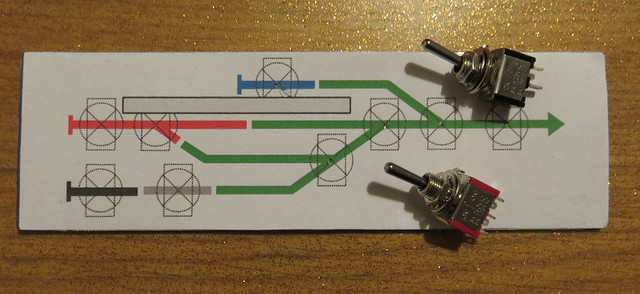
Before wiring can commence I needed to finish the control panel, which had been mounted into the front fascia of the baseboard. The schematic is laid out on the computer - I use Word, which has simple drawing tools that allows objects to be drawn to a measured size so the printed size is known. The drawing is duplicated, one has the switches drawn in place - ensuring there is space between them, and marking the centres. This print-out is stuck on the aluminium panel, and the centres of the switches punched.

IMG_2940

I then took the panel into work and used a pillar drill for the switch holes, and not forgetting the screw holes in each corner. These took a bit of cleaning up with various files.
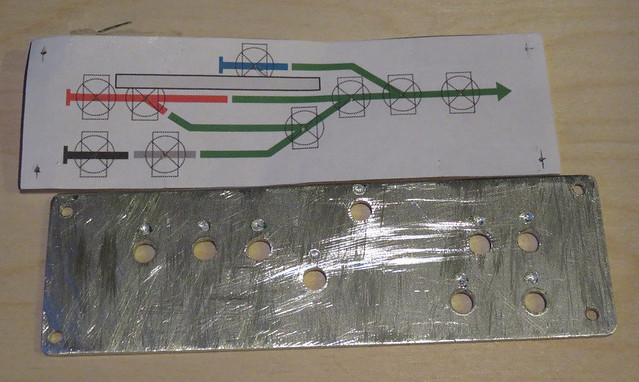
IMG_2941

On the back of the panel I also drilled a small hole part-way through above each hole, this is to locate the tab on the keyed washer that stops the switch from rotating. The second print-out (without the switches drawn on) is cut to fit, including switch holes, as is a piece of clear plastic. I used a piece of packaging, but anything clear, stiff, and about 10 thou thick will do. The switches are mounted through the three layers.
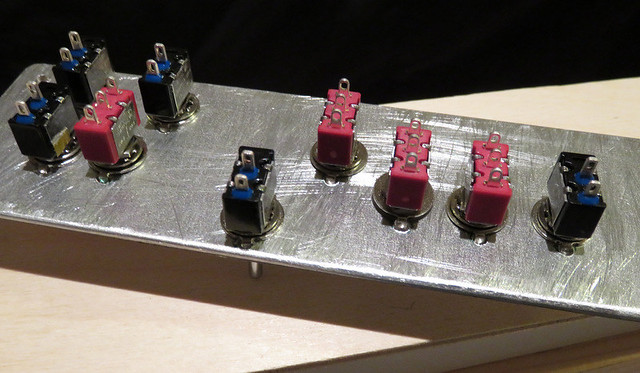
IMG_2942

With the panel screwed in place the result is a neat, easy to follow panel for surprisingly little effort. Recessing the panel means the edge of the plastic and paper layers aren't seen or vulnerable. I've added coloured rubber grips to the section switches to match the diagram, while point motor switches are left silver.
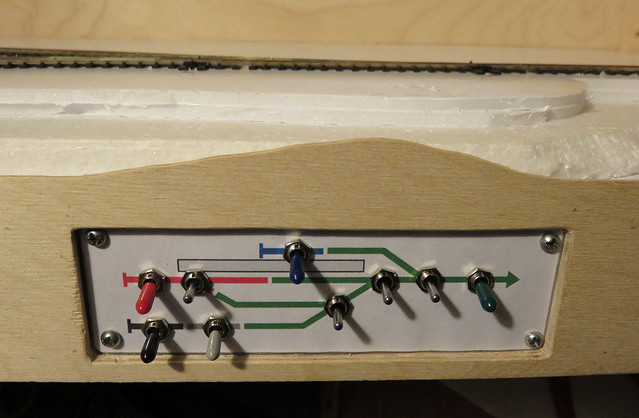
IMG_2992

Tuesday, 10 June 2008

Starting the 'lectrix


The first photo shows the fitting of the point motors and uncoupling magnets for the micro-trains couplers I use. For these the magnetic field has to be accross the track, and I have found that a pair of cupboard-catch magnets works well. They are available in bulk from B&Q or Homebase etc., and are easily dismantled to get the magnets out. These are stuck together and glued into an oblong hole I cut into the baseboard before laying the track (the holes were covered in paper and the track layed over the top).


The point motors are SEEP - with a built-in accessory switch I will use for the point frog polarity. I simply glue these to the underside of the board using Bostik, ensuring the operating rod is through the tie bar, the travel of the point motor is parallel to the tie bar and that the range of travel is cental to the point motor (important for the switch to operate). Here I have stuck the point motors to pieces of thin corrugated card stuck to the board, partly as the plywood was uneven where it had been drilled, and partly hoping to reduce noise - we shall see!


The second picture is the control panel I have just made. For such a small layout it is suprising how complex the wiring is! There are 7 point motor switches (silver), 4 main track feeds and 3 further isolating sections (with coloured caps to match the diagram). I was concerned that I would not fit them all in the space I had cut out of the front of the baseboard - but fortunately they just fit. The panel is an offcut of metal sheet from the scrap bin at work, drilled on a pillar drill in a lunchtime! The diagram is drawn on a computer (Word, nothing fancy) and printed out, stuck to the metal with Bostik. Finally a layer of clear plastic (the bubble pack from a Wills kit) is laid over the top, and the switch holes cut out with a scalpel.


I wanted the panel to be recessed into the cut-out in the baseboard, and it will be held there with a couple of M4 bolts, however access behind the cut-out is very difficult because of the board bracing! Still, it will look good.


Now I have started the actual wiring, so the next update should be when that is finished. I won't have much time in the next couple of weeks though, so progress may be slow!