Showing posts with label chassis. Show all posts

Sunday, 16 July 2023

Reviving the Haig - Part 2

Today I decided to investigate the running problem. The chassis seemed to run OK out of the chassis, but when I put it under load (holding it back) the worm started slipping on the gear. On closer inspection I realised the motor (and mount was twisting to the side, and could slip off the gear. After a little thought, I moved the motor over with another piece of 1mm plastic to the side of it. I also superglued the brass strip to the plastic packing beneath it, which is a tight fit between the "springs" on the tops of the frames so should help to prevent twist, and having noticed if the bolt was tightened too much there was a short, I stuck Sellotape on the underside of the brass as I suspect it can touch the springs. 

That improved things slightly and the loco ran up and down OK, but again if run under load the motor started slipping. This time I noticed that the motor could lift off the brass mounting plate. It's stuck with contact adhesive which remains a little rubbery, and it may not be helped by the motor which does run quite warm, so allowing just enough "give" for the gear to slip. 


After some more thought I figured the motor needed to be physically held down, and decided the easiest way was with a wire that could be tensioned. I drilled a hole in the brass each side of the motor and looped a wire through, twisting the ends together. I tried a copper wire but it snapped, then found a steel wire in my useful-wire-bits tin which could handle the strain, the ends were twisted with pliers until the motor was held down tightly. Of course the wire over the motor required some of the lead in the boiler to be ground away for the body to sit flat, and the twisted end needed to bent over and tucked carefully into the body when fitting the chassis, but it seems to work.

Running is still not quite as smooth as I'd like, there's a little hesitation at times and it can be prone to the odd stall which is odd given the 6-wheel pick-up all seems to work fine and I can't feel any binding in the chassis, although after a little more lubrication and when warmed up it seems acceptable. Perhaps a flywheel will help if I can find one to fit (needs to be 10mm diameter, 3mm deep, and 1.5mm shaft). 


Saturday, 15 July 2023

Reviving the Haig

 The Haig is in a bit of a sorry state. The body looks tatty, and appears to have had the cab rear fixed after a break, I'm sure this can be tidied up in due course. 


It looked a little nose-down to me too, an extra piece of plastic packing under the smokebox sorted that. Of course then the bolt which holds the chassis to the body - which was barely making a couple of turns into the nut anyway - was now too short. Fortunately I found another of the same thread (well it fitted the captive nut), but too long - so that had to be cut down with the dremel.

The plastic body was very light, although it did have a piece of lead under the read half of the boiler. I fitted a "Swiss roll" of roofing lead into the smokebox, and managed to slot pieces into the side tanks, the left side tank had only small gap at the bottom which I opened out slightly and "posted" in slices of lead wiped with contact adhesive. 

I fixed the motor to the brass mount with contact adhesive, which holds it securely enough, and wired it to the chassis frames. The brass motor mount is held in place by the bolt at the front, and a wire "finger" that slots below a lip on the right chassis next to the worm gear - this stops the motor rising up, at least in theory. 

So, does it work? Yes, but... it's a bit jerky, and the worm must be climbing the gear and pushing the motor up as it really grinds going forwards (smoother backwards). Sometimes it even stops and spins the motor. So much for that wire finger, I wonder if the brass can twist? It may not help that the drive is a little crude and has a fair amount of friction, even after a little lubrication, although there is no binding. I need to rethink that motor mount...

Tuesday, 31 January 2017

Disaster Recovery

Remember back in September, I was struggling with the valve gear on the WD Hunslet build? At the time I thought I'd nearly got there, but soon realised I hadn't. Whatever I did the loco didn't run smoothly, or stopped with some difficult to find bind. After several attempts at assembly and some useful advice via the NGRM forum, I discovered:
  1. The centre driving wheels were fractionally smaller than the others. This works fine, except that I'd managed to swap them to be the front set during the rebuild - leading to the loco rocking and poor pick-up problems
  2. The axles are linked by idler gears, with a little slack. However the wheels are linked with coupling rods, with a little slack. This makes it extremely difficult to assemble the chassis with the wheels quartered and the idler gears in place - and if one wheel is one tooth out, it may look OK but will bind
Just as I thought I'd resolved these issues and got the valve gear assembled correctly and started to test run the chassis, the con-rod and valve gear disconnected itself on one side. It seems that after the umpteenth assembly the return crank/crank pin has snapped at the crank pin, and had almost sheered across the crank arm too. This appears to be a cast part, and clearly not in a strong material, though to be fair it's a second hand chassis with lots of butchering having taken place.

IMG_2033

This left me stuck and somewhat down about the project. After all it would be a pretty difficult spare part to get, and really meant a complete set of valve gear was needed, so the project was shelved. However. a week or so back I was given another chassis by Martin Collins at a Sussex Downs group meeting. It was sans pony trucks, and he said it didn't run well (though he may have been trying to make me feel better about cannibalising it), but it did have complete valve gear, so I set about the transplant.

IMG_1643

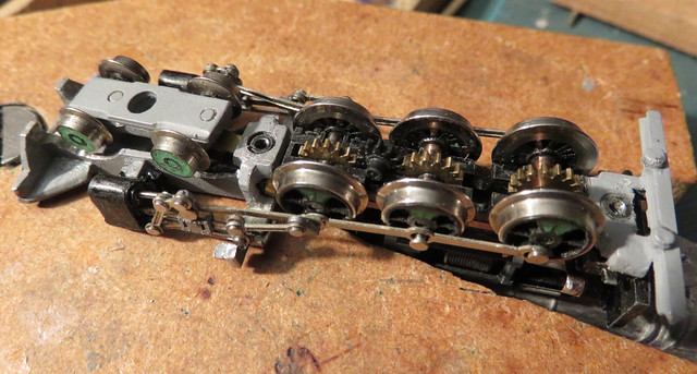
The first challenge was reassembling the chassis after removing the wheels to get the broken crank pin out. After the previous attempts, this time I knew I had to get the wheels and gears in mesh so the crank-pins aligned before fitting the coupling-rods. Sounds easy, but there's enough slop in the gears to make it not quite clear when they are aligned, while moving one axle meant one of the other axles or idler gears popping out - still, it only took a couple of hours this time.

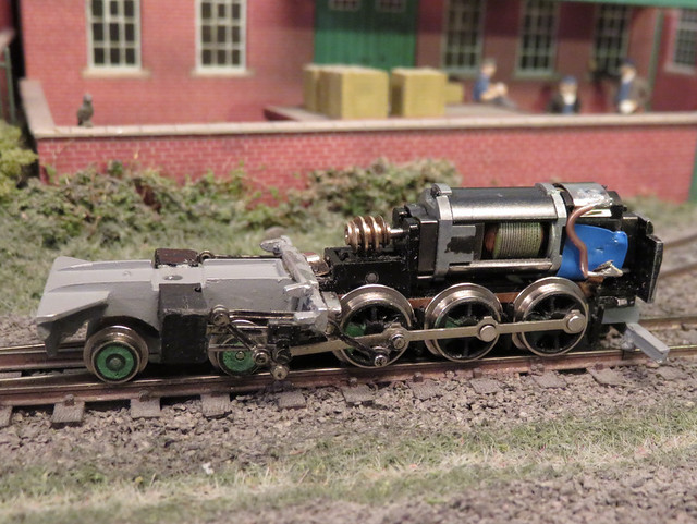
I noticed a couple of differences with the replacement chassis, apart from the motor being mounted vertically. The return crank/pin was made from the same stuff as the rest of the valve gear, possibly steel, and not cast from mazak or cheese or something. Also the eccentric rod that attached to the return crank was, at it's other end, slotted to move back and forth on a pin, rather than being jointed to a representation of the rocking die link. That saves a piece and a riveted joint, while the machined crank pin was probably more robust, so I guess this is a later "improved" (cheaper and stronger) version of the chassis.

IMG_2179

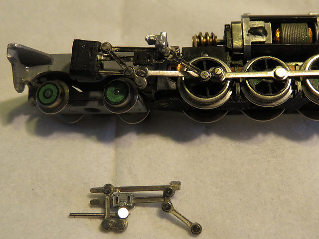
Here we have the new valve gear fitted, with the old gear below - note the extra link top right. But I still had binding, so much adjustment was carried out with the motor disconnected from the gears, rolling the chassis to detect any issues, and after some time I identified several causes:
  1. The slotted end of the eccentric rod could hit the crosshead if the piston was at the rear of its travel while the return crank was at its closest point of rotation. This meant setting the position of the return crank so the eccentric rod was further back, and tweaking the angle of the end of the slide bar so they didn't hit..
  2. The slotted end of the eccentric rod could hit the whitemetal cast outrigger that supports the valve gear at the upward end of it's movement. Careful filing of the casting was required, it now being rather thin at that location, along with care in positioning the valve gear assembly.
  3. If the slide rods are too far forward the slotted eccentric rod came to the end of it's travel and jammed, too far back and as well as that the wiggly bit (technical term) hanging from the crosshead pulled taut and jammed
IMG_2182

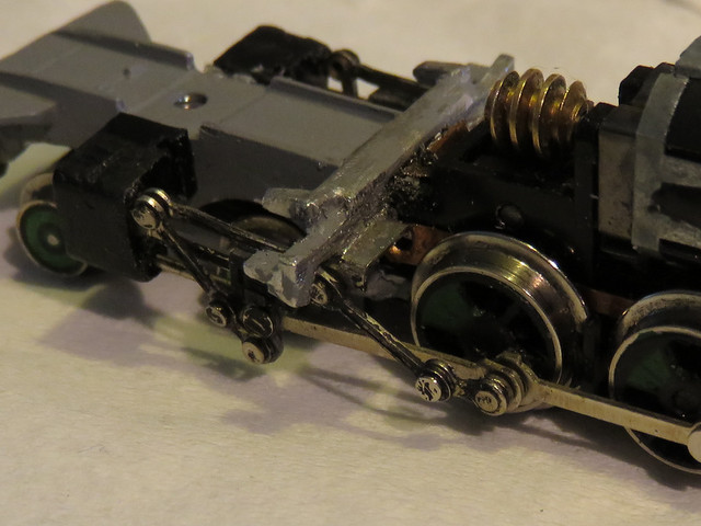
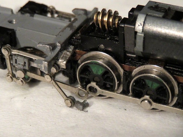
Close-up you can see how the bracket at the end of the slide bars sits on a ledge at the back of the cast cross-member, with the filed out slot for the slotted eccentric rod. Compare to the photo at the top of the page with the "original" valve gear.

IMG_2178

Finally I have an assembled chassis that appears to work without binding. It could do with some lubrication and extra weight seems to help the pick-ups,and of course the motor grinds away in the Minitrix way, but I'm hopeful I'm back on track...

Monday, 2 May 2016

Motor-Bogie Rebuild

At Sparsholt I spotted this on the 7mm NGA stand:


Branded Keykits I guess it's pretty old, but it looks like a Wrightlines motor bogie, which is currently unavailable (like much of the Wrightlines range, sadly). It's essentially a Tenshodo motor bogie replacement, but with a Mashima motor mounted with it's widest dimension vertical to allow the wheels to be pushed in to 14mm gauge - very useful given the number of 7mm scale kits that utilise the Tenshodo unit. This one had crudely fitted pick-ups, mismatching bolts and a broken wire - but the motor turns when it got power.


It didn't take long to dismantle. I checked and adjusted the wheel back-to-backs, and found some M2 bolts that were a good fit - the nuts are secured with Araldite. I moved the PCB down away from likely body fitting and closer to the wheels, and attached new pick-ups from phosphor-bronze strip - which I find much springier and more effective than wire. With the motor refitted, wires reattached, and keeper plate bolted in place the unit was running.


Now I know these things can be a little fast, with relatively high gearing, but a few lumps of whitemetal on top slowed it a little. The motor seems to run quite hot too, I don't know if it could do with more airflow. However it dos occasionally stop at low speeds, seemingly at the same spot, and I think more of a mechanical bind than pick-up issues - though I can't see anything wrong with the gears. I'm hoping some running in will help.

Monday, 5 January 2015

Atkinson Walker Steam Tractor

So here's a project I've already got on the go, albeit progress has been rather slow the last couple of months. I had a Halling chassis and having read the book on the Redlake Tramway, I thought an Atkinson Walker Steam Tractor would be an interesting model. These were vertical-boilered chain-driven locomotives, like the better known Sentinals they used road-vehicle ideas from the time, to make efficient and cheap shunting locomotives. Most were standard gauge but two were built to 3' gauge - the more famous one ended up on the County Donegal Railway in Ireland, where later rebuilt as a Diesel it was named Phoenix. More about that here, where I found this picture of the Redlake loco.


I'd wondered about a scratch-build in plasticard, which shouldn't be too hard apart from the curved corners. I might then have scaled down the body slightly from the 3' gauge versions, however looking at the dimensions I figured that although large, I could just about get away with it in 009. So to make life easier I picked up the Worsley Works scratch-aid kit at EXPO-NG.


As usual for these kits there's some etches for the body - and that's it, no under-frame parts, details, or instructions. The parts are obvious enough though, once I'd figured that the half-etch rebates in the top and bottom of the sides were to go at the outside, and allow beading to be added. So first I cut a hole in the footplate for the chassis to fit, then with the sides carefully curved around and soldered to the footplate and the tank-tops I found some 0.5mm brass wire that fitted into the rebate.


Bending to size, fitting, and soldering the wire was not a little fiddly! Some miniature clothes-pegs (no it isn't a 16mm scale model) from my wife's card-making oddments came in useful.


So the lower body looks OK, though there may be some more cleaning up of excess solder. I've got hand-rails to add in the doorways, then the upper body (windows) and roof to solder on. The roof will restrict access, though the body will be floppy without it, so I need to figure out what's going on below and inside first!

I have added a couple of brackets inside from scrap brass to centre the chassis in place, but I haven't yet figured out how to attach it. I tried making up brass clips to fit into the ends of the chassis, but that's tricky. I also need to make the underframe, which may be narrower than the motor, so I'm thinking of making frames and buffer-beams as a plasticard sub-assembly to which the chassis clips, and can be bolted to the body. Those springs are quite distinctive, any suggestions for suitable mouldings?

Sunday, 27 April 2014

Building a Tin Turtle

Having built the chassis I've been getting on with the protected Simplex (or Tin Turtle!) build. These locos were built in WW1 to haul supply trains to the front lines of the Western Front, and had 40hp petrol engines within an armour plated body. Some were sold on after the war for use in industry.

Before assembly the chassis retaining nut was epoxied in place, and I cut the square holes in each end for the Microtrains couplings. Then after some fettling of the joins to get the best possible fit I used epoxy glue to join  the whitemetal body parts, checking the body was square while it set.


The next job was to fit the chassis. I chose to use the Mk1 version of the Meridian chassis as it allowed the body to sit slightly lower, and left more space either end for the couplings. Also the Mk2 suited the other project better. I'd already soldered the mounting brackets to the chassis which is then retained by a bolt through the previously mentioned nut, but I found a little packing from 20 thou plasticard helpful, with small pieces of plastic to prevent sideways movement at the free end.


The above picture also shows how tricky it was to fit the couplings, I added a piece of 40 thou plastic inside each buffer beam and drilled a hole between that and the whitemetal to take the retaining screw. This leaves a minimal amount of the coupling body protruding and keeps the couplings secure, but one coupling needs to be removed to access the chassis retaining screw.


The next task was the etched roof, having chosen the "protected" version as I find it more interesting than the (easier to build!) fully armoured version. The parts are easy enough to fold up and curve, and I managed to solder the main parts together. The tricky part was soldering the wire supports in place while keeping everything square.


I did cop out of soldering the end overlays for fear of the rest coming unstuck, instead gluing them in pace afterwards. The whole thing was then epoxied onto the body, then the exhaust casting super-glued on top.


As you can see from this photo I've got it sat nice and low to the rails. The green patches are filler, though I'll have to get a coat of primer onto it to see if there are any other gaps.

Thursday, 10 April 2014

An Outside Framed Chassis

At Narrow Gauge South I headed straight for the 009 Society second-hand sales stand. The society had acquired a batch of chassis from the Minitrains Fiddletown & Copperopolis Locomotive, these are 0-4-0 steam loco chassis with outside frames. Of course to narrow-gauge modellers outside frames chassis are very useful, but almost unknown as a ready-to-run chassis. I'd also heard they are excellent runners so I had to have one!


The outside frames, with flycranks, are obvious and nicely made. The cylinders are rather American in style, easily changed no doubt, but the frames are of the plate-type so ideal for a UK outline loco. The cow-catcher will have to go but the long screw (that would go down the chimney) holds the front of the chassis, so might need some thought!

With the rear-hung motor and flywheel you's guess it is a very rear-heavy chassis, and indeed it pulls wheelies well! However with just a lump of blu-tak on the cow-catcher to counterbalance it, the flywheel and low gearing ensure the chassis purrs along beautifully; smooth, slow, and quiet. This will be a useful loco - but what loco should I build on it?


My first thought was the large Hunslet I have - this was one of the locos built in my teenage years on an Ibertren chassis. It could do with being tidied up but the chassis isn't a great runner, and with inside frames and small wheels I've never been happy with it - it needs outside frames! However as you can see, with the Minitrains chassis positioned so the motor is in the cab, the wheels and particularly the cylinders are too far back, and will look wrong in relation to the smoke-box and chimney. Shame...

I've also tried a Hampton Water Works Kerr-Stuart body kit (I've got a partially complete one in my bits box), but that wasn't a good fit either - it might be possible but very tight. I've already seen Kerr Stuart Skylark kits built onto this chassis (by James Couling and Charlie Insley), but I've already got one of them as a tram loco. Steve at Narrow Planet had a test 3D print of another Hunslet to fit this chassis, so there's another possible option. Decisions...

Tuesday, 25 February 2014

Meridian MPD18 Chassis Mk2

I mentioned back in November that I'd acquired two of the Meridian MPD18 chassis kits, but despite only having bought them a month apart, one was for the Mk1 design and the other the Mk2 design. I built the Mk1 already so I thought I'd build the Mk2 and see how it compared.

There are some important differences in the design:
1) Top-hat type bushes are supplied for the axles
2) The axles are fitted into the chassis from below after assembly with bushes and gears
3) The layshaft is assembled in it's own carrier and fitted to the chassis from above
4) The pick-ups are suggested to be fitted to the upper side of the chassis, as I did for the Mk1 but not as the Mk1 instructions suggested.
5) The brackets for fitting to the Meridian body kits that use this chassis are changed, and look much improved.


So here is the Mk2 assembled. No soldering is required except for the pick-up wires, and to attach the nut to the body fitting bracket (not shown), and can be put together in a couple of evenings' work. I did deviate from the instructions slightly:
- I used phosphor-bronze strip rather than the wire provided for pick-ups as I think it is more reliable with less drag
- I was concerned that the motor was not secure enough relying on the strap alone (there is no locating end-plate as on the Mk1) so used a little Bostik glue (the rubbery stuff) under the rear end.


Side by side (Mk2 on right) the obvious difference is the size of the motor, the newer one is small making the chassis narrower, though it is mounted higher so they are about the same height overall. The wheels are the same, I think they would look better and probably pick-up power better if they were of a larger diameter. A shorter wheelbase (or variable options) might give the chassis a wider appeal for other prototypes.


From the drive end (Mk2 on the left) it can be seen there is no motor locating plate, the newer design relies on the motor fitting into the chassis frames and the strap holding it secure. I think a locating plate as for the Mk1 design would be a good idea and the strap alone didn't seem to hold the motor securely enough.


From below the removable axles with bushes of the Mk2 (right) can be seen, the keeper plate is held in place by the bolt that secures the chassis to the body. As well as providing a better wear surface for the moving parts this design is a vast improvement in terms of assembly, as the worm-gears and the adaptor tubes (to go from 1.5mm dia axle to 2mm dia gear) can be super-glued in place before the axle is fitted to the chassis. The Mk1 chassis required holes to be drilled in the brass tube to let the super-glue in, then the tube and gear have to be glued to the axle as it is passed through the chassis - difficult to do, with a high risk of gluing the axle solid!

So overall the Mk2 version of this chassis is much easier to assemble and should be more durable and easier to service in the future.