Showing posts with label control panel. Show all posts

Monday, 23 September 2019

Paint and Light

Having added the back-scene, wing panels and lighting rig, the next step is to get out the paint and make it all presentable. The external surfaces of the layout used the same grey primer (Wilkinsons) as used on Slugworth and Hexworthy. And I mean the same paint, I bought a second tin to do Hexworthy but the original 1 litre tin from Slugworth had plenty left, and now it's done a third layout too! It does require two coats with a light rub-down in between but the slightly satin grey gives a good finish.


Sadly the pale blue paint used for the back-scene on Slugworth had run out, so I popped to the DIY store to find something similar, but without much luck in the wood paint ranges. The original tin was actually a left-over from the bespoke colour mixing service, from the bargain basket, actually an emulsion paint for walls but I had used it directly on the wood back-scene of Slugworth and it had worked fine, with a nice matt finish. So I checked out the bargain basket of left-overs. There was a 1 litre tin of "blue hoo" which was the first shade of blue from white - basically white with a blue hint - not quite blue enough, but it was £2.50 so I picked it up, along with a couple of tester pots of a light blue emulsion - these were then mixed in to make my own shade of pale blue!


The result is a very pale matt blue, and works well for a hazy sky background. I don't plan anything else on the back-scene, just the low-relief buildings. Ideally the back-scene would curve around the rear corners but that was impractical in this small layout (particularly due to the sector plate and buildings), but with a plain background the corners are not obvious.


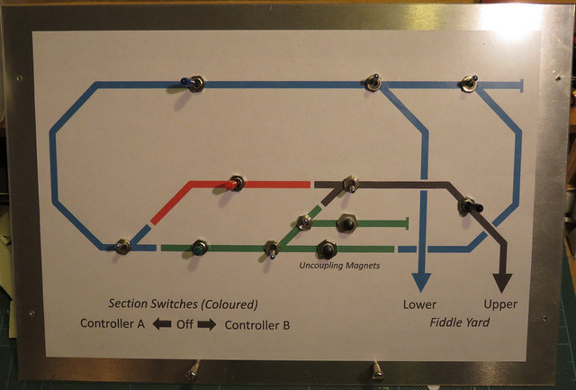
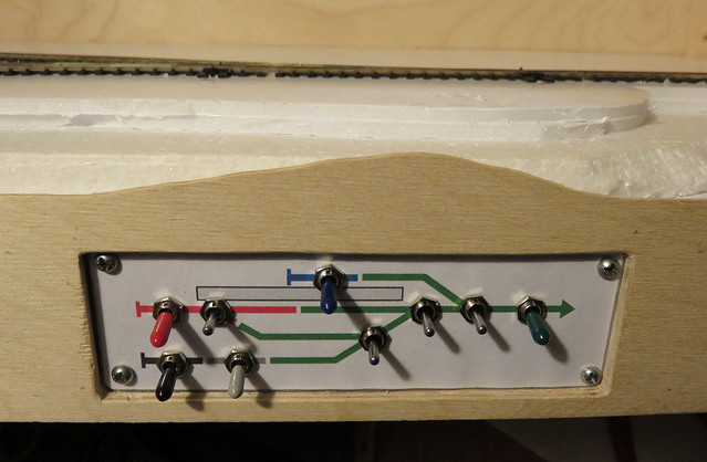
I'd removed the switches from the fascia for painting, before refitting I stuck a new print-out of the schematic diagram on with pritt-stick. Two versions had been drawn (in MS Word) - one with the outlines of the switches and marking-out lines, used for drilling holes, and this one without. The clear plastic was screwed on and the switches refitted through the holes from behind. The result looks tidy and is easy to follow (I hope) while being simple to make. Of course on testing it I'd got two of the switches swapped, but that was soon rectified...!


The final task for layout presentation was the lighting, again I used the left-over strip of "natural white" LED's used on both Slugworth and Hexworthy - full details can be found here. I have found that arranging the LED's to point straight down is not as effective as pointing them backwards. The lighting beam is arranged to sit an inch or so forward of the front of the layout, and angled so the inside of the fascia - where the LED strip is attached - is pointing down as well as back. Even so it seemed there was lots of light towards the rear and on the back-scene but items at the front were not so well lit, so I added short additional strips attached to a mounting at 45 degrees to the fascia - this means they are pointing down and back at about 20 degrees to the vertical. The mountings were knocked up from plasticard - quick, cheap and easy, but I had to take care soldering the wires to the strips!


The wires were then run back under one of the pivoted support arms to a socket, which was secured under the "tab" that rests on top of the end of the layout when the lighting is folded down. The socket accepts a standard wall-wart power supply.


So here's the finished layout "structure" seen from my standing eye level, and I've placed the buildings so far to get a feel for the scene. The folding legs lift the layout closer to the viewer, the back-scene cuts out background distractions, the lighting illuminates the modelled scene evenly, and the top fascia and side panels frame the scene, hiding the lighting and ends of the back-scene. All simple elements to add to a layout but really improve it's presentation. There are other ways of presenting a layout, but I would argue that some kind of backdrop and lighting are essential if a model is to be appreciated.

Sunday, 1 July 2018

Another Control Panel

If you've noticed that updates on my modelling activities have been limited of late, there are a couple of distractions that could explain things, and not just holidays and the hot weather.

The Sussex Downs 009 group are building a new layout, and I seem to have got the job of wiring it up, possibly because no one else seemed to want to. After some time thinking and planning I have adopted my usual approach of coding the wires, and using lots of terminal blocks, hopefully making it easier to follow - and debug in future. However, it became apparent that progress during fortnightly meetings was rather slow, so I brought home the control panel for some homework.

IMG_5064

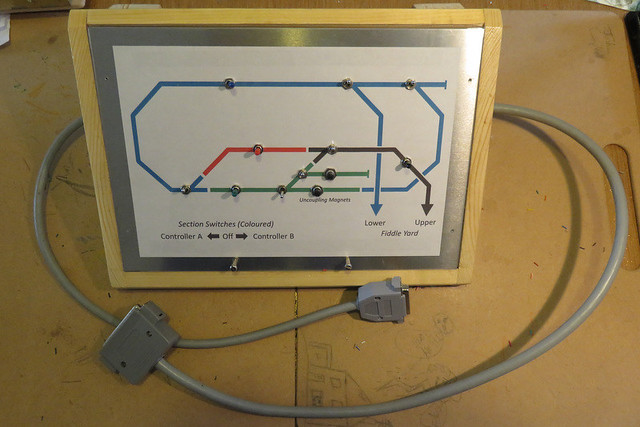
I can take no credit for the box itself as that is the work of Martin Collins, who has much better woodwork skills than I. The panel is my usual approach of a sheet of aluminium, with a computer printout schematic diagram, and a layer of clear plasticard on top. The coloured switches operate the track sections while the silver ones operate the points. The two grey cables run one to each of the two baseboards.

IMG_5067

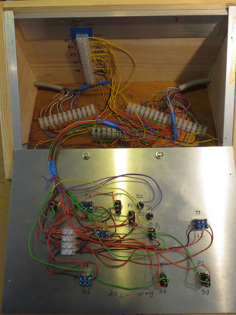
Inside (the panel is upside-down in front of it's box) may look messy, but the terminal blocks are labelled according to wire codes, and simply link the switches to the track, point motor, or appropriate power supply, so should not be too hard to follow. The incoming power connections have yet to be made, and the big cables need some kind of cable grip.

IMG_5065

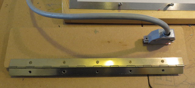
The multi-way connectors weren't much fun to wire up but I've not found a better alternative for this many pins, that isn't too bulky or costly. Each connects to a hinged panel on the back of the baseboard, one of which is seen here.

IMG_5066

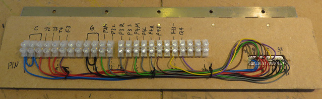
The back of the panel has more terminal blocks - which connect from the socket to the various parts of the layout. The seemingly random letters and numbers are the codes for each wire, the wires are colour coded according to purpose too. This panel will hinge down for easy access if required.

Saturday, 3 February 2018

Panel games

Here's another of my control panels. Not one of my layouts though, but the latest project by the Sussex Downs 009 group - and at about the size of an A4 sheet of paper, the largest I've made.

IMG_4368

The principles are the same as most of my layouts though, DC "cab control" (two controllers) through colour-coded sections, which are mounted along with point switches on a mimic panel. The panel is a sheet of 2mm aluminium onto which is mounted a printout of the diagram, and covered with a sheet of clear plastic - 20 thou sheet in this case due to the size, but thinner packaging plastic does smaller panels. So, now we just need to wire it up.

Monday, 8 May 2017

Panel Games

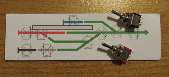
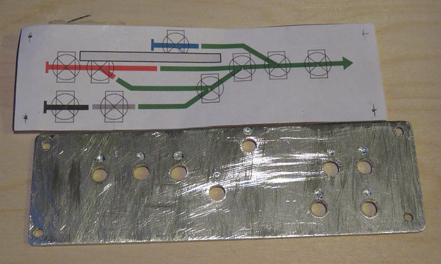
Before wiring can commence I needed to finish the control panel, which had been mounted into the front fascia of the baseboard. The schematic is laid out on the computer - I use Word, which has simple drawing tools that allows objects to be drawn to a measured size so the printed size is known. The drawing is duplicated, one has the switches drawn in place - ensuring there is space between them, and marking the centres. This print-out is stuck on the aluminium panel, and the centres of the switches punched.

IMG_2940

I then took the panel into work and used a pillar drill for the switch holes, and not forgetting the screw holes in each corner. These took a bit of cleaning up with various files.

IMG_2941

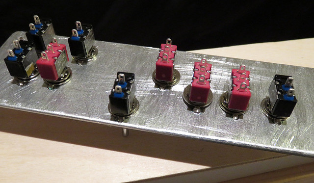
On the back of the panel I also drilled a small hole part-way through above each hole, this is to locate the tab on the keyed washer that stops the switch from rotating. The second print-out (without the switches drawn on) is cut to fit, including switch holes, as is a piece of clear plastic. I used a piece of packaging, but anything clear, stiff, and about 10 thou thick will do. The switches are mounted through the three layers.

IMG_2942

With the panel screwed in place the result is a neat, easy to follow panel for surprisingly little effort. Recessing the panel means the edge of the plastic and paper layers aren't seen or vulnerable. I've added coloured rubber grips to the section switches to match the diagram, while point motor switches are left silver.

IMG_2992

Saturday, 15 April 2017

Baseboard Finishing Touches

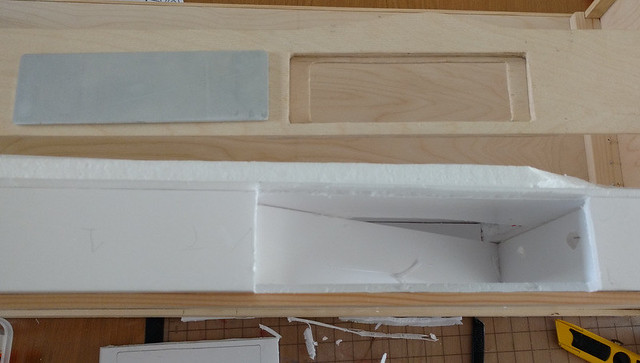
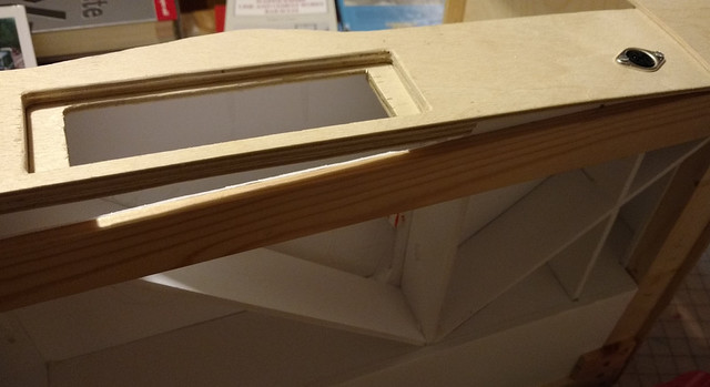
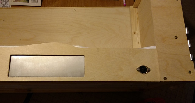
Hexworthy will need a control panel, and like Awngate, the best place seemed to be the front fascia. The layout will sit on a shelf and be front operated, and the fiddle yard adjoins the end, so other than the hassle of a separate control box, it's the only logical place. The panel is a scrap of 2mm aluminium from the guillotine at work, which happens to be an ideal size, but normally I'd fit it to the rear of the fascia for neatness. Here though there wouldn't be space for it to be removed from behind for access to the switches, so it had to go in from the front - so to maintain a neat appearance I decided to recess it into the fascia.

2017-04-14 17.50.11

Here's my piece of aluminium, with some trial printouts of the panel layout. These aren't yet final, but show it will all fit. The fascia (bottom) has had a suitable sized hole cut out, with two other layers cut too, one to the size of the panel, and one a little smaller.

2017-04-15 15.07.04

The two layers are glued behind the fascia creating a 6mm deep recess which the panel just fits, and a support which it will eventually be screwed to. These two layers also reinforce the thin ply edges so this is not a weak point. Meanwhile, the foam-core board is cut away with a knife to make space.

2017-04-15 21.18.29

Fitting it together, you can see how the foam-core structure and the timber reinforcement conspire to make access from the rear so tricky. I've also added a socket for the power connections at the same time.

2017-04-15 21.17.55

All fitted together. I need to drill the panel for the holding screws, when I drill it for the switches too. I've also cut and fitted the "wings" that frame the sides of the scene, and hide the untidy bits like split hinges and back-scene framing.

2017-04-15 21.21.47

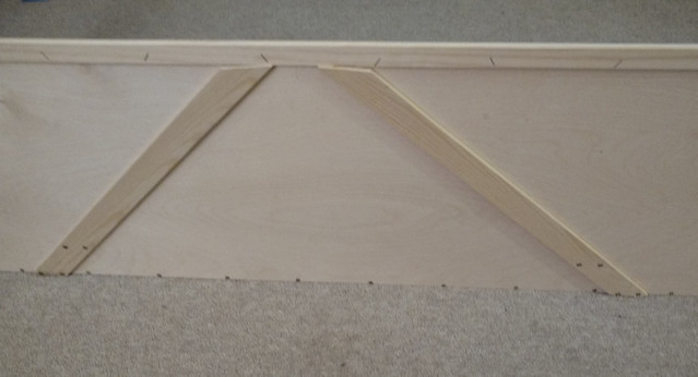
Talking of the back-scene, I've used some offcuts of the thin timber strip to brace it. These are screwed to the lower reinforcement, glued to the ply back-scene, and stapled through from the front. The ply back-scene is much stiffer now, with no tendency to bow.

2017-04-15 21.22.34

So there we have it, one tidy looking, solid, yet surprisingly lightweight base-board. I do need to add a lighing beam - when I've decided what lighting to use - but for now I can proceed to track-laying!

Monday, 22 December 2014

Knobs and Switches

It struck me that in order to run trains from either oval to the station, and to be able to shunt the station while running trains on the main lines, the wiring for this train set was way beyond connecting a controller to each circuit! I decided I'd better allow for three controllers, even if two would suffice most of the time, which meant having to have rotary switches rather than just 2-way. I settled on 4 main sections that can be switched to any controller, and 7 sub-sections that allow locos to be isolated. Hopefully the control panels make this all clear, and it will allow enough flexibility in operation.


I made up two control panels by printing out a schematic drawn in MS Word. These were mounted on some thick plastic sheet I'd picked up somewhere, then covered in sticky-back plastic (very Blue Peter!). I'd already drilled holes for the switches so they could be fitted, then I wired the switches to a loom ending in a screw terminal "choc-block" before fitting the panels to the layout.


The panels are fitted into the side of the station board, the plywood being cut away to clear the switches and allow the wiring through. The Gaugemaster controller in the middle provides controllers A and B.


With the screw connectors stuck in place (hot glue works well for this) wires are run to the relevant tracks on the layout, and the "temporary" connections of the two circuits to the controllers changed to the switched arrangement.


Further screw terminal blocks were used on each board and wires run from the feed rails to them, via small holes next to the rail, then they were connected back to the blocks by each panel. As the boards are permanently joined I haven't bothered with connectors, though the cables could be released from the terminal blocks if needed, provided they were labelled to aid re-connection! As you can see different coloured wires are used to help identification, it certainly makes wiring up easier. For example I used:

  • Blue: Common return (all outside rails)
  • Red: Main switched sections
  • Orange or Yellow (when I ran out): sub or isolating sections
Plus whatever other colours I had to hand for the controller feeds.


Another block connects the panels to the controllers, and joins all the "common returns" which greatly simplifies the wiring. There is a sticky label by each terminal block with wire codes marked on. The DIN plug on the left is connecting the third controller (C) to a 5-pin DIN socket.


As I've used the same socket as on my other (more serious) layouts, and connected the 16V AC from the Gaugemaster controller, I can use one of my usual hand-held controllers, such as this AMR example (left). However I've also wired a plug to the end of an old Hornby controller, which works surprisingly well. Either way the third controller can be used by someone outside the layout, so friends (and visiting grown ups) can operate without having to squeeze into the centre well.

So after a little planning and careful wiring, I was pleased when the layout worked first time. Even better my Son is very happy, he got the hang of the somewhat complex control knobs quite quickly, and he enjoys running trains in and out of the station from the main line. He's also enjoying shunting the goods sidings!

Tuesday, 10 June 2008

Starting the 'lectrix


The first photo shows the fitting of the point motors and uncoupling magnets for the micro-trains couplers I use. For these the magnetic field has to be accross the track, and I have found that a pair of cupboard-catch magnets works well. They are available in bulk from B&Q or Homebase etc., and are easily dismantled to get the magnets out. These are stuck together and glued into an oblong hole I cut into the baseboard before laying the track (the holes were covered in paper and the track layed over the top).


The point motors are SEEP - with a built-in accessory switch I will use for the point frog polarity. I simply glue these to the underside of the board using Bostik, ensuring the operating rod is through the tie bar, the travel of the point motor is parallel to the tie bar and that the range of travel is cental to the point motor (important for the switch to operate). Here I have stuck the point motors to pieces of thin corrugated card stuck to the board, partly as the plywood was uneven where it had been drilled, and partly hoping to reduce noise - we shall see!


The second picture is the control panel I have just made. For such a small layout it is suprising how complex the wiring is! There are 7 point motor switches (silver), 4 main track feeds and 3 further isolating sections (with coloured caps to match the diagram). I was concerned that I would not fit them all in the space I had cut out of the front of the baseboard - but fortunately they just fit. The panel is an offcut of metal sheet from the scrap bin at work, drilled on a pillar drill in a lunchtime! The diagram is drawn on a computer (Word, nothing fancy) and printed out, stuck to the metal with Bostik. Finally a layer of clear plastic (the bubble pack from a Wills kit) is laid over the top, and the switch holes cut out with a scalpel.


I wanted the panel to be recessed into the cut-out in the baseboard, and it will be held there with a couple of M4 bolts, however access behind the cut-out is very difficult because of the board bracing! Still, it will look good.


Now I have started the actual wiring, so the next update should be when that is finished. I won't have much time in the next couple of weeks though, so progress may be slow!