Showing posts with label controller. Show all posts

Tuesday, 5 September 2023

Rethinking power supplies - Slugworth simplification

A while back I discovered that a simple Hornby "wall-wart" transformer could be used to power my layouts, a much neater and more compact solution than an open-frame transformer mounted in a home-made power box (see below). So I thought it worth getting another. This one is a Hornby C912 rather than the C990, it's rated 16V AC at 14VA which I make to be 875mA, so pretty much the same as the C990 which is rated 800 mA at 16V AC. Either type can be bought on ebay for less than £10. 

When I made the "micro" power pack I'd just hard-wired the power lead in, but it seemed neater to fit a plug and socket, and allow the transformer to be interchangable - not least as I like to have a spare at exhibitions. The transformer comes with a 2.5mm (inner) x 5.5mm (outer diameter) power connector, so I used a matching socket from Squires, and refitted a matching plug to the existing transformer. 

Now the folllowing gets a bit involved! There is a risk with these connectors in that the LED layout lighting uses the same/similar type for 12V DC. In fact, the 12V transformers seem to use 2.1x5.5 plugs which strangely fit 2.5x5.5 sockets, very confusing. I think if I adopt 2.1x5.5 sockets for the lighting they will still work with the 12V DC lighting supplies, but while the AC supply 2.5x5.5 plug will fit the socket the inner contact will not be made. This all seems a bit odd! In any case, some clear labelling may be needed. 

The convenience of the wall-wart transfromers has made me rethink my power box strategy. The original design provided not just 16V AC to both controller and layout, and so 12V DC from the controller, but also a high-frequency track cleaner, and a capacitor discharge unit (CDU) for points, all fed to the layout via a 6-pin DIN plug. The idea was that it kept all the complex and relatively expensive components together in a box that can power any of my layouts, rather than having to add them to each layout. 


Now, I no longer use a high-frequency track cleaner, modern motors don't like them and anyway the use of graphite on the rails has made them redundant. I've also found that the points on a small layout can be driven via a simple CDU made of 3 components in a choc-block connector, as provided in the mini power box seen above. However, some layouts - such as Slugworth - use manual points control and don't even need the CDU, so the mini power box is now simply a junction box. Clearly, it can be eliminated altogether...

So Slugworth has been modified by the addition of a 16V AC input socket for the transformer. This is wired into the 6-pin DIN socket. Now a 5-pin DIN controller plug will fit a 6-pin DIN socket, and fortuitously when I first wired my power box leads I matched the controller 12V DC and 16V AC pins between the 5 and 6 pin connectors (although for the controller the 16V flows in, from the power box it flows out). So here the controller can plug into the 6-pin socket and both it and the auxilliary 16V AC supply (e.g. for lighting) are powered from the plug-in wall-wart transformer, with no external junction or power pack needed. 

Of course, as the existing wiring is unchanged the power box can still be used with the controller plugged into that, and no separate transformer is plugged into the layout. This seems a bit complex but hopefully the diagram makes sense.

I did add a thermal trip to the 16V AC supply, I expect these sealed transformers have one built in but better safe than sorry. This trips at 1.6A which may be a bit high, but if there is a short it should trip. 


This view underside of Slugworth shows the existing socket (left) with the controller plugged in, and on the right the new power socket for the 16V AC transformer wired to both the controller socket and to the lighting power circuitry. Of course this is how many people already wire up their layouts, but the approach I've used maintains "backward compatibility" for the existing power box to be used instead, or as a back-up. 

This simple modification could be made to any of my smaller layouts to eliminate the need for a separate power box (and another lead), and just use a cheap wall-wart transformer. Layouts that need a CDU for point control could have the simple circuit added on-board too, although for now the micro power box used on Loctern Quay does that job. 

Friday, 16 June 2023

Controller testing

The Sussex Downs group recently passed on most of the Upsands Downs and Everleight Railway to a new owner, including some of the venerable hand-held controllers. It was observed that we could do with some new controllers to ensure we have sufficient for the new layout, and perhaps to give better performance. However, the choice isn't clear, with increasing ready-to-run options and modern N-gauge chassis being used with small modern motors, and many of them using coreless motors, as well as models using traditional motors, any new controller has to be able to deal with a wide range of mechanisms. So, I took along my collection of controllers to try out. 


Here's the under construction club layout which allows a continuous run, but has 12-inch radius curves on 1 in 30 gradients, so makes a reasonably demanding test track. 


Some of the locos used included a modern RTR Bachmann (the Baldwin), an old US N-gauge Bachmann "Brick" Plymouth chassis (under the tram loco), a Fleischmann Picolo (under the green tank), and the ancient Minitrix 0-6-0 (under the saddle tank). We also tested a Backwoods Darjeeling loco, which I think has a Mashima motor, and a Conway Castle using the newest Kato 110 chassis with a coreless motor. I think the Baldwin may also use a coreless, the rest are traditional motor types and some are quite crude by today's standards. We ran the locos alone, without a train, in this quick test. 

The subject of suitable controllers for coreless motors is often met with some confusion and potentially misleading information, even by loco and controller manufacturers, who usually state "feedback controllers are not suitable for coreless motors". I'm no expert so have tried to understand it through reading, and the answer really is not that simple. The key points as I see it are:
  • Feedback and pulsed controllers are not (quite) the same thing. A pulse controller may not have feedback, but a feedback controller is usually a pulsed type (as it monitors the back EMF "feedback" between pulses). 
  • The main coreless motor concern is overheating, since there's no iron core to dissapate heat, and the resin bonding the coils can (in theory) be damaged. Smaller "cored" motors can also be affected. Pulsed controllers are more prone to heating (than pure variable DC), and this is not limited to feedback controllers. An old non-feedback controller with a pulsed output (H&M Clipper?) could be damaging, while some feedback types are not - depending on the heating effect of the pulses. 
  • The other potential issue is that the feedback is not tuned to the low-inertia of coreless motors (or even small, low-inertia cored motors) leading to surging or jerky running. This is related feedback controllers only, and depends on the controller and the motor. This is why some controllers have switched feedback.
So, pulsed controllers are bad right? Well, the problem is pulsed controll (or PWM) is the best way to regulate motors. Giving full voltage overcomes the "stiction" (friction, magnetic resistance/cogging) in the motor, and in our case, any resistance in the pickup/wheel/rail interface, gear train friction, variable friction from motion, etc... so pulsed control allows for fine control at low speeds. DCC chips use pulsed control, as do most motor drives in other applications. 

So, how to have pulsed control without overheating? So far as I can tell, the factors are...
  • Peak voltage - some controllers actually peak at 16V or more!
  • Frequency - most controllers operate at 100Hz (rectified AC). Higher frequencies reduce heating apparently, but can cause noise. DCC chips operate at >20kHz (beyond the range of human hearing, does it bother dogs?). (I tried a Minitrains controller once which also operated at 20kHz, but it didn't seem to work well/smoothly with any motors except Minitrains - I don't know why)
  • Pulse shape - for reasons of complex physics I don't really follow, the sharper or more "peaky" the wave-form, the more heating is induced
So, coreless-friendly controllers aim to address one or more of these issues. For those who are interested, reading for more details:


Of course the club layouts use a different plug and wiring standard to my own layouts, so the first job was to make up an adaptor! Not very neat but it did the job. 
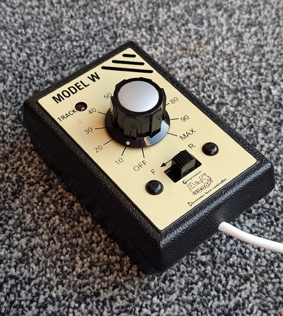

Gaugemaster W - pure DC control, rectified with variable voltage, which minimises motor heating. 
In our tests it works well enough with all motors, giving smooth running, but lacks reliable low-speed control. Locos could sometimes start with a jerk or stop abruptly, with no pulses to keep the motor kicking over, and some motors don't maintain a steady speed - they had to be "driven". 
The case is a little bulky and I don't like the slide switch as it's not kind to thumbs (horrible for shunting). 
This is a good, safe controller for coreless and smaller motors, and is ideal for continuous runs, but not in my view the best choice for low speeds such as shunting. 

(Gaugemaster used to also offer the HH - a traditional feedback pulsed controller. It had a very peaky high-peak voltage waveform which offered good low speed running for older motors, but really heats them up.  Not suitable for coreless then... in fact, they don't sell it any more. I had one in my early days of 009 modelling, but sold it when I got AMR controllers.)
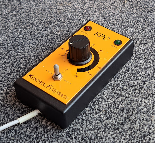
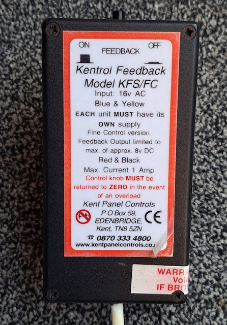

KPC - This is a pulsed feedback controller, but with a less peaky waveform and lower peak voltage than the HH. Mine is a "fine-control" model with switched feedback, and seems much kinder to motors than the HH used to be. I've used mine with coreless motors (feedback switched off/down - not sure if it is actually off or just reduced) and they seem to run fine, although my layouts don't exactly allow sustained running. I presume the switch just stops (or reduces) the feed-back regulation of voltage (or pulse width) in response to the back-EMF so it doesn't over-react to coreless motors with low inertia - the output is still pulsed so there may be some risk of motor heating. 
In our tests it gave excellent smooth control, including low speed and starting and stopping, thanks to its pulsed output. Locos maintained a steady speed. With feedback on locos run more slowly but some coreless motors surged or vary speed, switching the feedback off worked with all motors. My other KPC has a broken feedback switch, so I have left it in the "off" position. 
The slim case and toggle switch mean it fits neatly in the hand and is nice to use single-handed for shunting.
This is my favourite all-round controller, although probably not advisable to use it for sustained running of coreless motors just in case. Sadly no longer available*, it is surprising (and telling) how many exhibition layouts I notice are using KPC controllers!
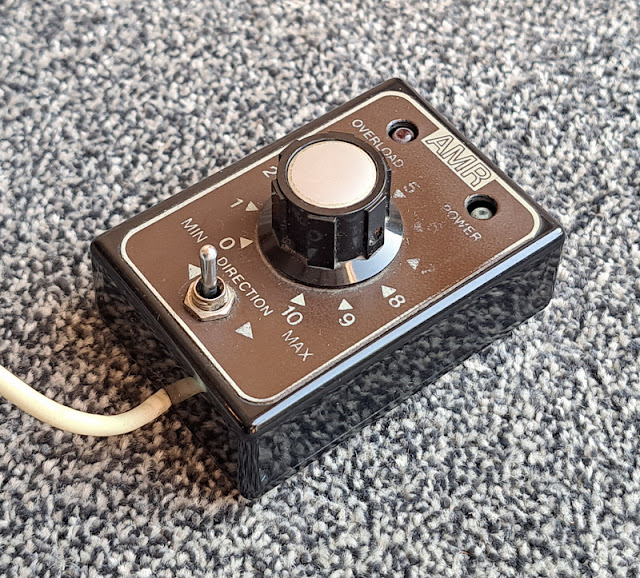

AMR - This is a also pulsed feedback controller. Some years ago I saw several controllers compared with an oscilloscope, and the AMR and the similar Trax controller (which I don't have) have a very similar output to the KPC (with feedback on), and with similar characteristics. Interestingly, Nigel Lawton recommends one as being suited to the coreless motors he sells (http://www.nigellawton009.com/TraxFC1.html), alhough Trax themselves say it is not suited to coreless motors! In reality, I reckon that like the KPC, the AMR and Trax would be fine to use with coreless motors for short periods as Nigel says, but sustained low speed running may cause motor heating. 
Since the behaviour is generally similar to the KPC (good low speed control and steady speed) but without the feedback switch, we didn't do extensive tests at the club. 
It has really nice ergonomics with it's dinky case and toggle switch for easy shunting and one handed operation. Sadly long out of production, although the similar (in size and performance) Trax is available. 
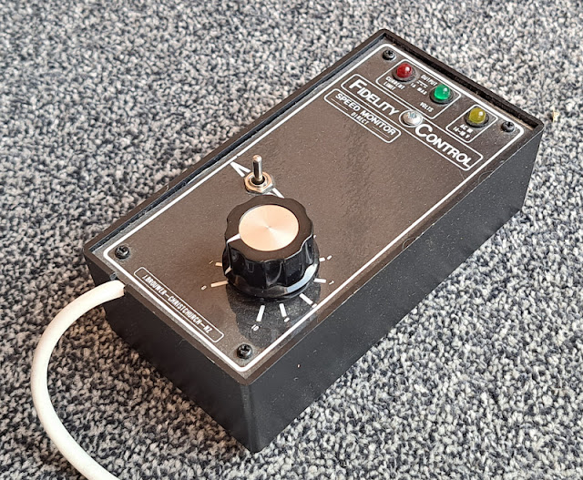

Fidelity - this is a rare one, hand-made in New Zealand! As I understand it, the pulsed output varies in amplitude as well as pulse width and has a waveform designed to minimise heating, to be suitable for cored and coreless motors. It does use feedback, I'm not sure the technicalities but it's more advanced than traditional controllers. It was also available with simulation (inertia and braking) but mine does not have this. 
In our tests it worked very well with good low speed control and speed control. It was at least as good as the KPC, and of course is safe for all motors without needing to switch anything.
The case is large and clumsy, and while it has a toggle direction switch it isn't really possible to use one-handed. 
So perhaps the ideal controller - the only real issue apart from the ergonomics is that it too is no longer available!

Conclusion? Well, the W is a safe option for all motors, but a feedback pulsed controller (of which the Trax is the only one currently available) gives better low-speed control albeit with the possible risk of overheating coreless motors. The ideal would be a Fidelity in a smaller more ergonomic case! I'd settle for the KPC being available again*. With the range and complexity of DCC systems now on the market and considering what must be possible with modern electronics, it is surprising no manufacturers have looked again at the analogue controller market.

*I'm aware All Components are listing a KPC-like controller, I believe using the original KPC circuitry, but there's little information and they don't list the fine-control switched-feedback model. 

Tuesday, 15 October 2019

Upgraded powerpack

I have two "power-pack" boxes for my layouts, a large one and a small one, and when I take a layout to an exhibition I take both in case of failure - though it hasn't happened yet! However with two layouts going to Uckfield I wouldn't have a spare. The large box was always intended to hold a second transformer, but I had never needed to fit one - well now seemed a good time.


Inside you can see the original transformer on the right - made by AMR it has two 16 V AC and a 24 V AC output, the latter is used for the capacitor discharge unit (CDU) for point motors seen at the rear. One of the 16 V AC outputs is used for a hand-held controller which plugs into the box, the other provides power to accessories and also the high-frequency track cleaner seen in the foreground. The new transformer is fitted rear left, it's a Gaugemaster T1 with two 16 V AC outputs allowing a second controller to be powered. Note the circuit breakers directly fitted to the outputs. The track cleaner has two outputs and could be wired into the second controller, but since adopting graphite it is rarely used so I haven't bothered.

So two controllers can be plugged into the box by 5-pin DIN plugs, and two 6-way DIN outputs each provide the controller output, 16 V AC for accessories, and the CDU output for point motors. Some years ago I posted the schematic below:


The new transformer effectively duplicates this circuit with a second transformer, controller, and output, except that there is still only one CDU feeding both outputs, and I've not bothered to wire the track cleaner to the second controller. It can thus power two layouts, or one layout needing two controllers.


Here are both power-pack boxes together. I made up a new 6-way lead to connect to the layout, my spare was made from single-core telephone wire and I'm amazed it hasn't broken already - so now I have 3 leads. I've also adopted a colour code to make plugging in quicker and easier - blue is the layout connection, red is the controller, tape on the cables and sharpie pen on the sockets.

The small box contains a single transformer (2 x 16 V AC) and a high-frequency track cleaner, providing a single controller and accessory supply in a small package ideal for micro layouts. Until now my small layouts have mostly had manual point control so there is no CDU, but I'm thinking of adding one if it will fit, or removing the rarely used track cleaner to make space.


As well as the new transformer I have a new controller, a Gaugemaster W. Unlike most of my other controllers this is not a feedback type or pulsed output controller, but simply a smoothed DC output, and so is ideal for coreless motors which are becoming more common. Initial tests show it doesn't have good slow speed control - at least of conventional motors - which I expected, but also it didn't maintain a steady speed, so it doesn't seem as good as my other controllers. However it may be better with coreless motors and safer for continuous running.


As you can see I now have quite a collection of controllers. As well as providing a choice of controller type depending on layout and loco type, it means I can always have a spare available for a show. This proved useful at the last Wealden group show when a broken wire caused issues, easily fixed but not something you want to address at the show!

Friday, 3 May 2019

Broken wires

Back at the Steyning show in March, while running Slugworth, we had a problem. The loco kept stopping and going, it got so bad we took everything off the track thinking there was an intermittent short. Then it twigged that the problem was in my hand...


It doesn't take a genius to figure that the wires shouldn't look like that! Fortunately I always take a spare controller, so this one got tucked out the way awaiting repair. The other day I had the soldering iron out fixing some microphone leads for church (mic leads seem to fail regularly), so thought I'd have a go at fixing the controller too.


The lead is retained by a zip tie trapped inside the box, the rubber shroud on the cable is meant to protect the lead from flexing too far at the entry, but clearly that has failed. The four wires then go to various parts of the circuit board. The board was fixed, possibly only by the knob and switch, but it wasn't obvious. So rather than try and remove it to de-solder the wires, and to save the length of wire I'd have to cut out, I decided just to cut out the broken section and re-solder the wires together.


Easy enough, but I didn't have any heat-shrink to protect the wires, and I didn't think insulation tape would protect them from each other and the circuit board. Time to improvise with some short lengths of plastic tube slid over the join and held with a spot of Bostik. The whole lot were then wrapped in insulation tape, and a new zip tie attached tightly to the cable to hold it in place.


I thought I should attempt to replace the rubber shroud to protect the cable at the entry to the box, but I didn't have rubber tube. The best I could find was a short length of another size of plastic tube which could be fitted tightly into the hole, and held with a spot of glue, while the cable was a tight fit inside. It remains to be seen whether this will do any good!

So the KPC is back in business, which is great as it's one of my best controllers in feedback mode. This one has a switchable non-feedback mode which should make it ideal for coreless motors, but when switched to that mode locos just shoot of at speed with the knob at zero. I've tested the output and the minimum is 4V in non-feedback mode - I've no idea why, or how to fix it, or why it doesn't affect feedback mode!

Monday, 22 December 2014

Knobs and Switches

It struck me that in order to run trains from either oval to the station, and to be able to shunt the station while running trains on the main lines, the wiring for this train set was way beyond connecting a controller to each circuit! I decided I'd better allow for three controllers, even if two would suffice most of the time, which meant having to have rotary switches rather than just 2-way. I settled on 4 main sections that can be switched to any controller, and 7 sub-sections that allow locos to be isolated. Hopefully the control panels make this all clear, and it will allow enough flexibility in operation.


I made up two control panels by printing out a schematic drawn in MS Word. These were mounted on some thick plastic sheet I'd picked up somewhere, then covered in sticky-back plastic (very Blue Peter!). I'd already drilled holes for the switches so they could be fitted, then I wired the switches to a loom ending in a screw terminal "choc-block" before fitting the panels to the layout.


The panels are fitted into the side of the station board, the plywood being cut away to clear the switches and allow the wiring through. The Gaugemaster controller in the middle provides controllers A and B.


With the screw connectors stuck in place (hot glue works well for this) wires are run to the relevant tracks on the layout, and the "temporary" connections of the two circuits to the controllers changed to the switched arrangement.


Further screw terminal blocks were used on each board and wires run from the feed rails to them, via small holes next to the rail, then they were connected back to the blocks by each panel. As the boards are permanently joined I haven't bothered with connectors, though the cables could be released from the terminal blocks if needed, provided they were labelled to aid re-connection! As you can see different coloured wires are used to help identification, it certainly makes wiring up easier. For example I used:

  • Blue: Common return (all outside rails)
  • Red: Main switched sections
  • Orange or Yellow (when I ran out): sub or isolating sections
Plus whatever other colours I had to hand for the controller feeds.


Another block connects the panels to the controllers, and joins all the "common returns" which greatly simplifies the wiring. There is a sticky label by each terminal block with wire codes marked on. The DIN plug on the left is connecting the third controller (C) to a 5-pin DIN socket.


As I've used the same socket as on my other (more serious) layouts, and connected the 16V AC from the Gaugemaster controller, I can use one of my usual hand-held controllers, such as this AMR example (left). However I've also wired a plug to the end of an old Hornby controller, which works surprisingly well. Either way the third controller can be used by someone outside the layout, so friends (and visiting grown ups) can operate without having to squeeze into the centre well.

So after a little planning and careful wiring, I was pleased when the layout worked first time. Even better my Son is very happy, he got the hang of the somewhat complex control knobs quite quickly, and he enjoys running trains in and out of the station from the main line. He's also enjoying shunting the goods sidings!

Tuesday, 19 May 2009

Layout Powerpack

There has been some discussion on the NGRM forum recently about controllers people use. Since I don't have a lot of time for modelling at the moment, I thought it would make an interesting post to describe the powerpack and controllers I use.


I claim no originality for this idea - I got it from a book by Cyril Freezer, and I'm sure it is widely done - but I liked the idea of the main components of the electrics being in a separate box. This keeps all mains wiring in a box on the floor, and also most attractively, allows the expensive bits to be used for many layouts! I made this one with my Dad years ago, when my trainsets evolved into model railways, so I reckon it has powered 8 layouts now ...


Anyway the basic principle is to provide the layout with all the power sources it needs, in this case a controlled 12V DC for the track, a pulsed 20V DC for points (i.e. a CDU), and a 16V AC supply for anything else - though so far I haven't found anything that needs it! My powerpack contains a transformer with 2 x 16 V AC outputs, both protected with thermal circuit breakers (this is very neccessary to avoid blowing the transformer in the event of a short-circuit), a Capacitor Discharge Unit for points (can't recall the make), and a high-frequency track cleaner (Gaugemaster). The latter can be switched out, in case of delicate motors! The schematic below should make all this clear.


All this is contained in a sturdy wooden box, the mains cable is clamped, fused at plug, with a neon to show the power is on, and of course the transformer is earthed. Some vent holes, a handle, and a couple of hooks to provide somewhere to wind up the cable complete it. There are two DIN sockets, a 5-way is the standard for hand-held controllers (16 V AC in, controlled 12 V DC out), and a 6-way for the lead to the layout. Each layout then just needs a socket for power in. See photo below.


In fact I have a second powerpack, an ultra-small one for very small layouts (one of my layouts is not much bigger than this powerpack!) containing just a transformer and track-cleaner. Points need to be manual, or as on Southon Yard, I built a simple CDU into the control panel for the single point with a rectifier and capacitor! If you wanted to avoid doing mains wiring, you could mount a cased transformer onto a board or in a box containing the low-voltage wiring.


The photo also shows the hand-held controller, in this case an AMR. They are long since out of business I believe, but I picked up a second one second-hand recently. I also have a Gaugemaster "HH" which is very similar, but I prefer the toggle direction switch of the AMR to the slide switch of the HH - it is kinder to the thumb! I also think the AMR gives better control, but I have no way of measuring it! Both are of the "feedback" type which I find gives good low-speed control. I don't run loco's far or for long on my layouts, so I have never seen any overheating issues that some find with feedback controllers and HF track cleaners.

Posted by Picasa