The lamps come with a circuit board to drive them and the instructions say it can be powered by voltages up to 16V A.C. However, I have a similar pack of lamps by Gaugemaster for another project, with an apparently identical circuit (I think they are made by the same people), but the instructions for those say on no account to use 16V A.C. such as the accessory output of a controller, as the peak voltage can be much higher. I guess I could have found an old "wall wart" to power it, but my standard power feed to a layout includes the 12V controller output, plus a 16V A.C. feed from the second winding of the transformer, so it made sense to use that. But to be safe I figured a preliminary voltage regulator would be a good idea, in case the circuit wasn't happy with the 16V A.C I would have made one myself but for under £2 I found a ready made circuit on eBay - a no-brainer really.
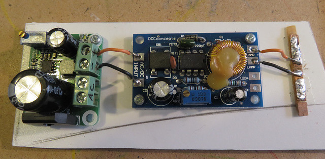
This circuit board is seen on the left, and can be adjusted to give between 3.3 and 12V D.C. with the little screw, from up to 20V A.C. We set it to 12V using a multimeter to check the output, and connected it to the input of the lamp driver, with both circuits screwed to a small piece of board.
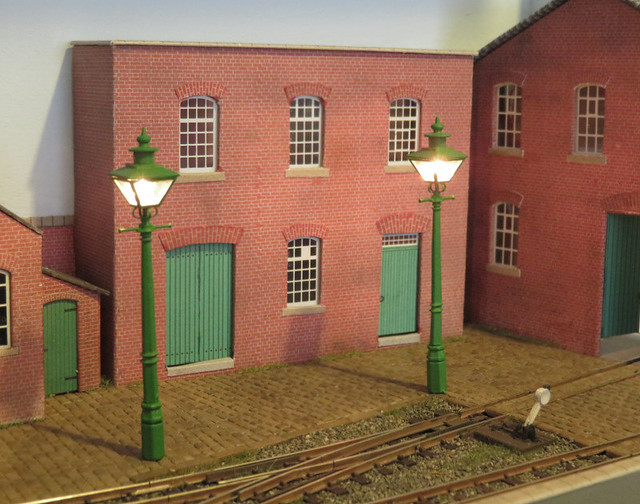
The lamps come with fine enamelled wires, which can be soldered without having to remove the insulation, so we used strips of PCB sleepers to attach them to. Having tested them with the circuit we mounted them on the layout, the instructions say a 2.75mm hole is required, but that must be if the lamp is used without a base, as can be seen the tube that extends below the base is very fine - about 1mm diameter.
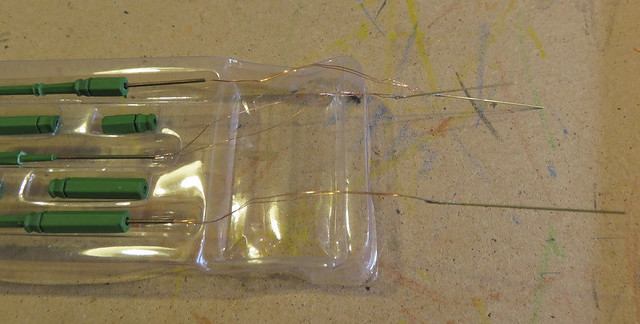
The problem was threading the fine wires through such a small hole in the baseboard (two layers of foamcore board). My solution was to tack-solder them to a length of stiff wire to act as a needle as seen above, pass them through the hole, then remove the wire with a touch of the soldering iron. The lamps are held well by friction, but we added a blob of hot glue where the tube exits the board to secure them.
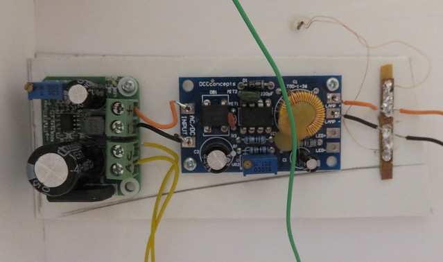
The piece of board with the two circuits on was then glued to the underside of the layout, and we made the wiring connections, which included a push-button on the front of the layout to switch them on. The lamp wires were connected via strips of PCB, and finally, we powered up the layout to check them out.
No comments:
Post a Comment