Of course this was an ideal use for the latching fiddle yard design I built a mock-up for recently. At the end of each track a 2.5mm brass tube "pin" was pushed through a slightly undersized hole in the deck (PVC foamboard in this case) on the track centreline, and a piece of PCB with a matching hole fitted over it with enough proud to solder to.
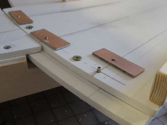
You can also see that the end of the traverser has a strip of foamboard underneath it forming a reinforcing lip, it fits under the fixed deck preventing the traverser rising - or in this case, falling when upside down. This means the brass pins go through 10mm of foamboard, then protrude about 4mm below.
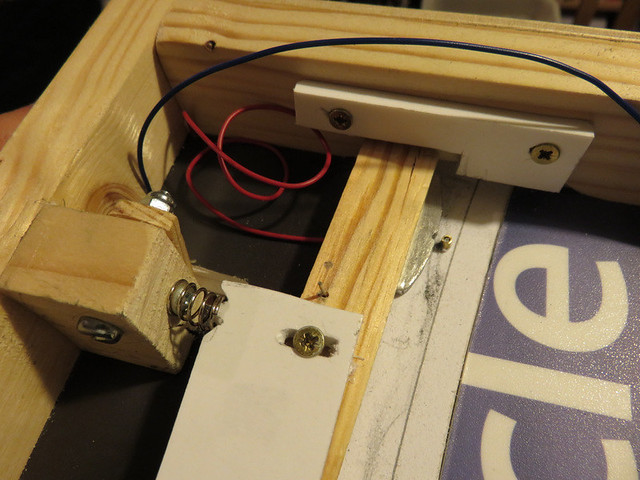
From underneath the curved strip attached under the lip of the traverser is clear (helped by the printed face of the foamboard - it came from the marketing department at work!), with the three pins protruding. The latch lever is on the left not yet fitted. A piece of aluminium about 3mm thick has been cut and shaped to a "D" with a notch in the centre of the curve and fixed to the end of the wooden lever, note the red wire attached to the aluminium. Also visible is the spring (from an old pen I think), the bolt for the release lever, and the paperclip that joins the release lever to the latch lever. High tech stuff you know.
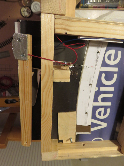
Here's the lever in place, bolt pivot at the bottom (with locking nut), and held by a piece of foamboard at the free end so it can slide. The foam wedge attached to the lever presses on the spring so the aluminium latch is pressed against a brass pin or the end stop, the screws allow some tension adjustment.
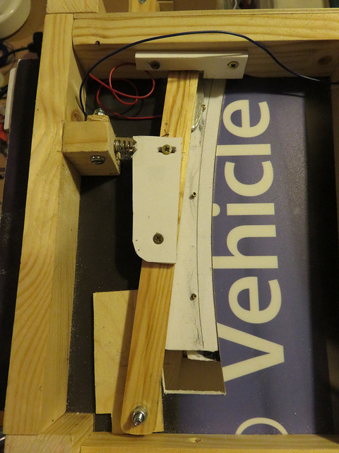
A close-up of the latch, here it's being held just clear of the brass pin compressing the spring, by holding the release lever (pivoted by the bolt seen on the left) which pulls the latch away.
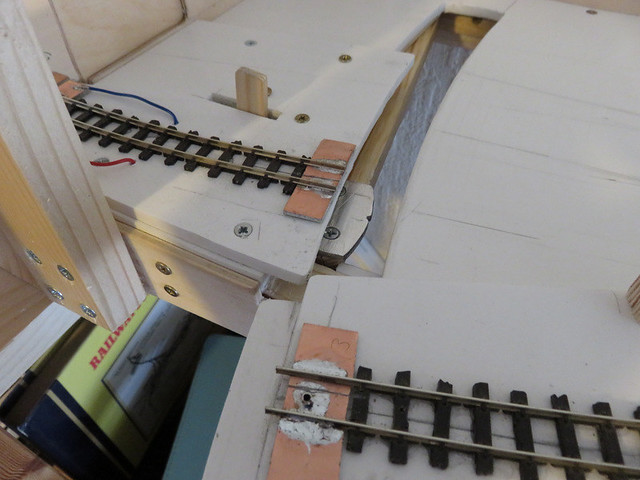
Above the board with the traverser swung clear the latch can be seen beneath. The traverser is simply moved until the latch catches a pin, and a track is aligned. The release lever is next to the track, pushing it left pulls the latch away from the pin so the traverser can move without jerking (it can be moved away from the latched position with a little force, the release makes it smooth). The PCB not only retains the track at the end of the traverser, but as seen from the position of the isolating break, feeds the near rail, the far rails being connected together via a flexible cable at the pivot end of the deck.
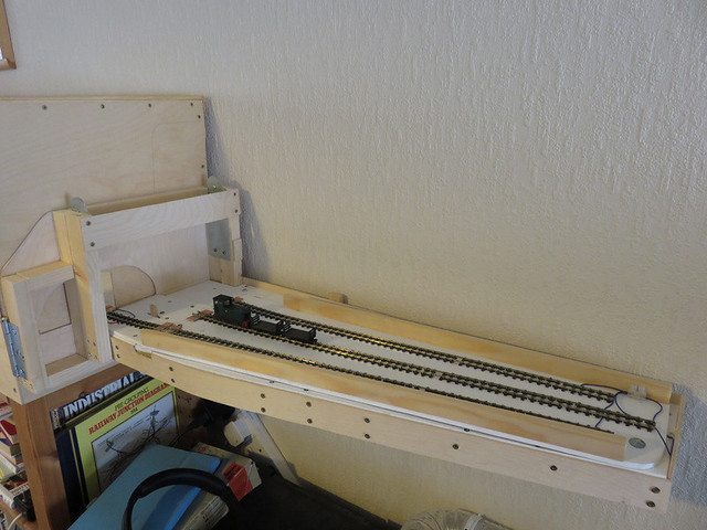
With all track laid a works train prepares to leave the centre track. I reused some track recovered from a fiddle yard years ago, though after spending time removing unwanted solder connections and cutting various bits to length I wished I'd just used a couple of new lengths!
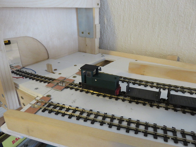
So another over-complicated fiddle yard is complete, but it should work well and does meet the aim of being compact and discrete.
No comments:
Post a Comment