Hexworthy has just four points, I've labelled A to D. Each has a feed to it's frog (in this case, the wire dropper from the PECO points) which is switched by the point motor, and I've labelled them Af, Bf, etc. There are 5 switched track sections labelled 1-5, I put the feed into the rear rail (as the wire is less visible) and only gap that rail, so fewer "common return" feeds (labelled R) are required. Because of the live frog points breaks are required in both rails of both joins between the red and green sections.
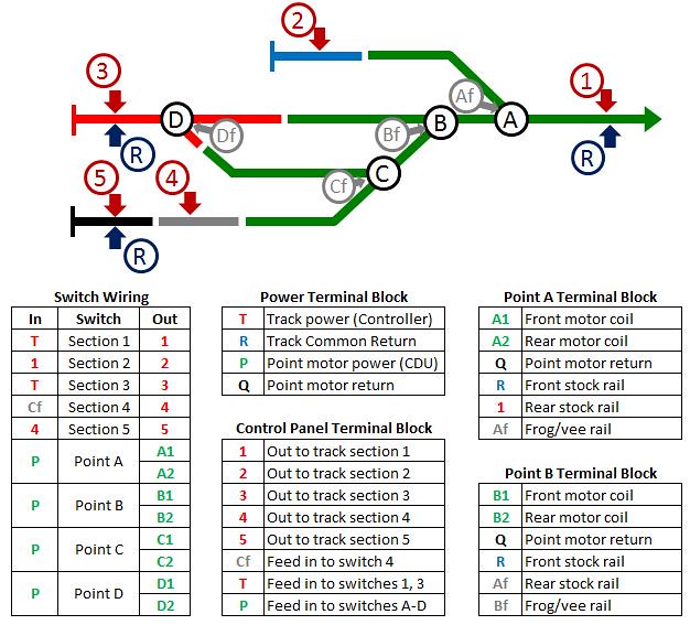
The switch wiring schedule is pretty straightforward, the table above shows the wire codes for the input and output of each switch. "T" is the controller track output, and "P" is the point motor power from the capacitor discharge unit (CDU). Note that the sections may be fed from the adjacent track, so for example section 5 is only live if section 4 is switched on and point C is set to the siding, as well as switch 5 being on.
Wiring to and from the switches is via screw terminal blocks that make the wiring easier to follow, make joining wires easier, and providing a point to de-bug if needed. There are terminal blocks for the incoming power supplies (from a 6-pin DIN socket), the connections to the panel, and as shown previously - one for each point motor which includes the frog switching as well as the motor connections. From the track plan it can be seen which rails are being switched, so the inputs come from the section, return, or previous frog feed - this saves extra wires to the rails. Example terminal block connections are shown above, the colours indicate the wire colour used.
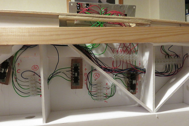
This is the result with all the wiring in place - surprisingly complex for such a simple track plan! At the top of the picture the control panel is lifted out to access the switches at the rear, below it the terminal block feeding the switches can be seen. On the right are the connections to the power socket, note that the return wires are linked over two terminals to make room for multiple connections. Below and left can be seen two of the point motor connections. All terminals are labelled with the wire code denoting the connection to switch, point motor, or track, so wiring up is simply joining the dots.
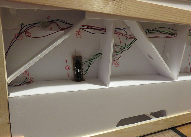
The other end of the board is a little less busy. All that remains is to tidy the cables, bundling together with tie wraps or a twist of wire, and securing where necessary.
You can see I've cut a slot in the foam-core, that's a hand-hole. I was finding it difficult to find places to grip when moving the layout around!
Up top the markings for the feed wires can be seen - and if you look closely, the wires can be seen soldered to the rails. I feed the wire through a hole in the board and form the end into a "7" shape, tin the end, and hold it against the rail web while pressing a soldering iron against it until the solder flows - hopefully giving a neat and secure join.
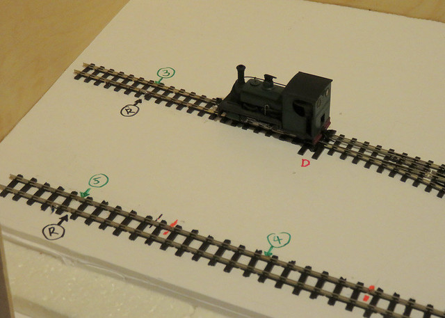
The loco is on a test run. I'm pleased to report it all worked first time! The careful planning has paid off.
No comments:
Post a Comment