I got to the Wealden Railway Group's little exhibition in Arundel today, with both kids and (grand)parents in tow. I say little as it is in a small scout hut, but as the group concentrate on small layouts, they squeezed 11 layouts in, plus demo and static displays. It's always a friendly and welcoming show too, with a free cup of tea/coffee included in the entry price.
Svanda is a Norwegien (or was it Swedish?) HO layout by Nigel Hill and Chris Ford. Rural charm up to their usual excellent standard.
This was an excellent example of a shunting layout in OO - small, well scenic'd, and interesting to operate. I can't remember the name though!
What if the Isle of Wight had narrow gauge railways and happened to be located in the Caribbean? That was the concept behind Puerto Paseo.
Another EXPO challenge relic - this time a Pizza depiction of a French tramway by Simon Hargreaves.
For a fuller set of pictures click here - though I haven't yet downloaded the many pictures the kids took on their cameras. If you like blurry, over-exposed and indecipherable images let me know.
Michael Campbell's blog about his model railways. Building model railway layouts in 009 (OO9) scale
Saturday, 8 March 2014
Tuesday, 25 February 2014
Meridian MPD18 Chassis Mk2
I mentioned back in November that I'd acquired two of the Meridian MPD18 chassis kits, but despite only having bought them a month apart, one was for the Mk1 design and the other the Mk2 design. I built the Mk1 already so I thought I'd build the Mk2 and see how it compared.
There are some important differences in the design:
1) Top-hat type bushes are supplied for the axles
2) The axles are fitted into the chassis from below after assembly with bushes and gears
3) The layshaft is assembled in it's own carrier and fitted to the chassis from above
4) The pick-ups are suggested to be fitted to the upper side of the chassis, as I did for the Mk1 but not as the Mk1 instructions suggested.
5) The brackets for fitting to the Meridian body kits that use this chassis are changed, and look much improved.
So here is the Mk2 assembled. No soldering is required except for the pick-up wires, and to attach the nut to the body fitting bracket (not shown), and can be put together in a couple of evenings' work. I did deviate from the instructions slightly:
- I used phosphor-bronze strip rather than the wire provided for pick-ups as I think it is more reliable with less drag
- I was concerned that the motor was not secure enough relying on the strap alone (there is no locating end-plate as on the Mk1) so used a little Bostik glue (the rubbery stuff) under the rear end.
Side by side (Mk2 on right) the obvious difference is the size of the motor, the newer one is small making the chassis narrower, though it is mounted higher so they are about the same height overall. The wheels are the same, I think they would look better and probably pick-up power better if they were of a larger diameter. A shorter wheelbase (or variable options) might give the chassis a wider appeal for other prototypes.
From the drive end (Mk2 on the left) it can be seen there is no motor locating plate, the newer design relies on the motor fitting into the chassis frames and the strap holding it secure. I think a locating plate as for the Mk1 design would be a good idea and the strap alone didn't seem to hold the motor securely enough.
From below the removable axles with bushes of the Mk2 (right) can be seen, the keeper plate is held in place by the bolt that secures the chassis to the body. As well as providing a better wear surface for the moving parts this design is a vast improvement in terms of assembly, as the worm-gears and the adaptor tubes (to go from 1.5mm dia axle to 2mm dia gear) can be super-glued in place before the axle is fitted to the chassis. The Mk1 chassis required holes to be drilled in the brass tube to let the super-glue in, then the tube and gear have to be glued to the axle as it is passed through the chassis - difficult to do, with a high risk of gluing the axle solid!
So overall the Mk2 version of this chassis is much easier to assemble and should be more durable and easier to service in the future.
Wednesday, 19 February 2014
Awngate at Shepton Mallet
Last Friday night featured, as forecast, gales and heavy rain, especially along the South Coast. Not the ideal evening then to load up the car and set off along the South Coast and into sodden Somerset for Narrow Gauge South West. However after a cautious drive with only a couple of minor floods, a fallen tree and a diversion, we made it safely to Shepton Mallet.
Awngate behaved well bar the odd reluctant coupling, so the effort the previous week was worthwhile. However with an hour to go before the end of the show a point motor failed - not one to a siding that could be ignored, but that from the platform to the run-round loop, necessitating some unusual working practices to keep things running! Still there were a lot of kind comments, and it was great to see a number of familiar and new faces. A big thanks to Tim Sanderson for riding shotgun and sharing the operating.
There were a lot of great layouts at the show, though I was particularly touched by the Wipers Fish Hook & Menin Railway by Matt Wildsmith. This is no romantic view of the Western Front, it is full of atmosphere and tragedy, but superbly modelled in S-Scale.
It was nice to see John Wooden's Isle of Stoner layout as featured on his Blog, it is surprisingly small but full of detail, like this corner featuring a plant nursery with hand-worked line!
The Clee Valley Railway by Peter Leadley is a little unusual as it depicts a 15" pleasure line in O9 scale.
There were lots more great layouts but I'll leave you to browse the whole collection of my photos - though I'm sorry I haven't had time to add captions yet!
Thursday, 13 February 2014
Awngate braced for a Storm!
The layout is as ready as it will be, and I'm packing up for Narrow Gauge South West in Shepton Mallet. However the weather forecast is for gales and heavy rain, including when I'll be loading the layout into the car and unloading Saturday morning. So it seemed wise for some last-minute thinking about protection for the layout.
Apologies for the poor photos, but the solution is simple. Two black bin-bags are opened flat (but left double-thickness) and taped together, then taped to the back of the back-scene. The lighting bar makes a helpful rail to drape them over and some tape at the ends should stop too much flapping about. We shall see how effective this is, but it is better than a rain-splattered sky, uprooted trees, and missing roofs. That would be just too realistic!
If you can get to the show it promises some excellent layouts, and do say hi...
Tuesday, 11 February 2014
Fixing and Fettling
I've always been frustrated with the poor running of the Skylark I built a year or so back. The Kato chassis just didn't seem to perform as well as other people's, and indeed the one I have under the railcar, it would run smoothly at speed but stall frequently at lower speed. I'd checked the wheels were clean and all appeared to be in order, but running didn't improve. It would be nice to have it running well for the Shepton Mallet show next week, so last week I took the loco along to a Sussex Downs group club-night and with the help of others we set about a diagnosis.
Eventually, as suspected, we traced the problem to the pick-ups. Although they looked fine, they clearly weren't making good contact, there may have only been one working pick-up each side. We found the only way to fix this was to remove the white clips on the top of the chassis (carefully, they can ping!), and ease up the pick-ups where shown with the yellow arrows. We did one end at a time, and as well as cleaning the pick-ups I tweaked their shape to have more of an outward splay, before feeding them back in behind the wheels. While the chassis was apart we applied a tiny drop of oil to each worm too.
The result is a chassis that runs as smoothly as it should, without stalling and controllable down to a slow speed. Since I was rather pleased with the way the body came out, it is great to finally have the loco running as well as it looks!
Spurred on with that success, I thought I'd address the uncoupling magnets. The Neodymium magnets I had tried in two locations really hadn't worked, they are actually too strong - wagon wheels and coupling tails shoot towards them, sometimes resulting in derailments. However in trying to excavate them I managed to damage the track - it didn't help that there are double rail-gaps and cut-about sleepers over the hole in the board for the magnets, but having rails sticking in the air was never going to work! And with a week to go before an exhibition this is not ideal.
Fortunately I managed to bend the rails back flat (it was the fishplates that had bent) and added a new "spare" Peco sleeper. A piece of paper was glued in place under the track (to support ballast), then the original cupboard-catch magnets inserted from below with lots of hot-glue to hold it. The glue-gun was also used to stick the tips of the sleeper to the baseboard. By this point the track looked like it would at least support trains!
I dug out some fine ballast and tapped it into place between the sleepers, not too thick to not limit the magnetism, but enough to cover the paper and glue lumps! Finally a little acrylic paint was mixed up and slopped over the lot to blend it in. The colour may not be an exact match, but I've tried not to be too even anyway so it looks fine.
Phew, disaster averted. Back to cleaning wheels and testing stock...!
Labels:
009,
Awngate,
Kerr Stuart Skylark,
track laying,
uncoupling magnets
Thursday, 30 January 2014
A tour of Thakeham Tiles
I've not a lot to show this month, there has been some activity preparing Awngate and stock ahead of the NGSW show next month, but wheel cleaning and scenery hoovering don't make an exciting blog post. However I do have this photographic tour of Thakeham that I never got around to showing after it was finished. Click on the photos for a bigger view.
The foreman watches on as the skips are filled with sand under the hoppers. The track in this area is almost buried under spilt sand. The loco is a Hudson Hunslet built in the mid 1950's.
Looking down from the top of the path to the hoppers we see the train climbing the gradient to the tipping shed, the two colours of sand in the skips can be seen clearly. The loco is passing the engine shed on the left, while on the right pallet-loads of concrete blocks, kerb-stones, and paving slabs await dispatch.
That last picture has been posed to match the photo on the cover of Graham Lelliot's book about the line, which was the inspiration for this model. I think I've captured the essence of the site, though as you can see, I could do with a lot more pallets of concrete products!
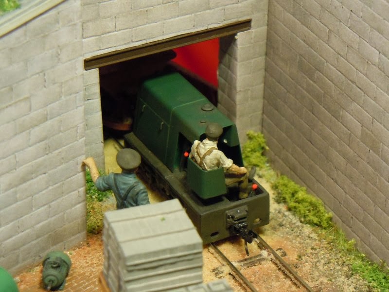
As the train passes the engine shed we see that another loco waits in the doorway, perhaps it has been pushed out for maintenance under better light, or just to make more space for work in the shed? This is a pre-war O&K and is showing it's age with flaky rust breaking through the paint, while the newer Hudson is a little grubby but well kept. In the foreground the "portable" track sections can be discerned, with steel sleepers and even the fishplates visible. In places wooden sleepers can be seen under the steel ones, though the sand does seem to get everywhere!
On the footpath that crosses the site a Labrador listens to the rumble of the train over the steel bridge above, as it enters the tipping shed. Or has he seen a rabbit? His master waits nearby.
The bridge still stands today, though there are no trains, just a conveyor belt. (The striped beam in the foreground carries a pipe, and I omitted it from the model)
In the yard a local team of builders have arrived to pick up some paving slabs, though they seem to be distracted arguing about whose turn it was to clean the van. In the background are rows and rows of concrete slabs, and piles of pallets waiting to be used. The footpath cuts though the site on the left.
At the end of the day the skips have been left near the hoppers, while a spare skip wagon is in the siding by the shed. The skip body is upended in the bushes, presumably to prevent it filling with water. The O&K has been pushed back into the shed - mysteriously, it also seems to have turned around!
Thakeham Tiles will be at the SWING narrow gauge show in Bognor on the 17th May.
The foreman watches on as the skips are filled with sand under the hoppers. The track in this area is almost buried under spilt sand. The loco is a Hudson Hunslet built in the mid 1950's.
Looking down from the top of the path to the hoppers we see the train climbing the gradient to the tipping shed, the two colours of sand in the skips can be seen clearly. The loco is passing the engine shed on the left, while on the right pallet-loads of concrete blocks, kerb-stones, and paving slabs await dispatch.
That last picture has been posed to match the photo on the cover of Graham Lelliot's book about the line, which was the inspiration for this model. I think I've captured the essence of the site, though as you can see, I could do with a lot more pallets of concrete products!
As the train passes the engine shed we see that another loco waits in the doorway, perhaps it has been pushed out for maintenance under better light, or just to make more space for work in the shed? This is a pre-war O&K and is showing it's age with flaky rust breaking through the paint, while the newer Hudson is a little grubby but well kept. In the foreground the "portable" track sections can be discerned, with steel sleepers and even the fishplates visible. In places wooden sleepers can be seen under the steel ones, though the sand does seem to get everywhere!
On the footpath that crosses the site a Labrador listens to the rumble of the train over the steel bridge above, as it enters the tipping shed. Or has he seen a rabbit? His master waits nearby.
The bridge still stands today, though there are no trains, just a conveyor belt. (The striped beam in the foreground carries a pipe, and I omitted it from the model)
With the skips emptied into the appropriate chutes in the tipping shed the loco slowly pushes them back over the bridge, and past yet more concrete products.
In the yard a local team of builders have arrived to pick up some paving slabs, though they seem to be distracted arguing about whose turn it was to clean the van. In the background are rows and rows of concrete slabs, and piles of pallets waiting to be used. The footpath cuts though the site on the left.
The train rattles back down the grade to the sand hoppers, to repeat the process again and again. Behind the skips can be seen the steps up to the top of the hoppers, which are set into the old quarry, though now the sand arrives by road.
At the end of the day the skips have been left near the hoppers, while a spare skip wagon is in the siding by the shed. The skip body is upended in the bushes, presumably to prevent it filling with water. The O&K has been pushed back into the shed - mysteriously, it also seems to have turned around!
Thakeham Tiles will be at the SWING narrow gauge show in Bognor on the 17th May.
Friday, 3 January 2014
Happy New Year! Here's to a busy 2014...
Happy New Year to all readers! I notice many Bloggers are posting reviews of 2013. The modelling highlights of the year for me were completing Thakeham for EXPO in October, and the 009 Society Convention in September, plus seeing Landswood Park in print in the Industrial & Narrow Gauge Review. I also finished some interesting stock projects in 009 and O14, and got to some good exhibitions.
The end of the year was dominated by a house-move, things are now settling down but of course modelling time has been limited, and may be for a while yet, and much of my modelling tools and materials is still in boxes somewhere. However Awngate has been given a new home on top of an Ikea shelving unit in our new lounge/diner. One of those box-files also contains a layout!
Christmas has brought some interesting presents including a new controller (of which more later, but first I need to find a DIN plug), a Langley kit for a WW1 Hunslet loco, and a book about yet more obscure and interesting railways!
So with the projects I listed back in November yet to be tackled as well, I have plenty to get on with in 2014. It is looking like it will be a busy year, as I also have some exhibitions lined up:
This in addition to the DIY jobs that are being lined up, and once I have got around to decorating my son's bedroom he'd like a bigger train set!

- Awngate will be at Narrow Gauge South West, Shepton Mallet, on the 15th February, so I need to make sure it still works!
- Thakeham Tiles will be at SWING in Bognor, on the 17th May
- Awngate will also be representing the Sussex Downs 009 Group at a show in Patcham, Brighton, on 14th June.
This in addition to the DIY jobs that are being lined up, and once I have got around to decorating my son's bedroom he'd like a bigger train set!

Subscribe to:
Posts (Atom)