Saturday, 24 August 2019

Point motors and wires

After considering the various options I settled on point motors for the challenge layout (really must come up with a name!), partially as I happened to have 3 SEEP motors recovered from a previous project.


It's important that these point motors are fitted centrally to the point for the in-built switch (used for frog polarity switching) to operate correctly. I do this by packing the point blades with pieces of plasticard so the tie-bar is central, and using another piece of plasticard cut to fit between the motor coils with a hole in the centre for the operating rod, this ensures both point and motor are in the central position.


The motors I used had already had the operating rod trimmed, but were too long for this thin MDF. I didn't want to trim them further - partly as the metal is very hard, partly because a longer operating rod allows the motor armature to travel slightly further than the tie bar, which makes the switch operation more reliable. However I found a piece of 5mm foamcore spaced the motor just enough for the operating rod to be a perfect fit. The pencil lines are in line with the point tie bar, and allow the motors to be positioned in line with them. The motors are then fixed with contact adhesive, no screws seem to be necessary, checking the operating rod goes through the hole in the tie bar, the contacts are on the most accessible side of the motor, and before the glue dries fully, that moving the motor moves the tie bar and the motor switch moves from one contact to the other.


The wiring arrangement was worked out on paper first in my usual way - assigning a code to each section, point motor, and so on, so each wire has a code. The front panel was drilled and the switches installed (I'll detail the panel later), holes drilled next to the rails where feeds were required, and a couple of terminal blocks stuck in place under the baseboard with hot glue. I then labelled every feed wire hole, switch, and terminal with the code for the wire connecting there, in this case I even colour-coded the labels to match the wires (using the kids' felt-tips!)


Feed wires are passed up through the holes and soldered directly into the web of the rail. This isn't as scary as it first seems:

  • Strip about 6-8mm of the wire, twist and fold into an L-shape
  • Tin the end of the wire with solder
  • Bend the wire so it nestles into the side of the rail, ideally holding itself but if necessary hold in place with a screwdriver while soldering
  • Apply the iron with a tinned tip to press the wire into place, wait until the solder goes liquid and seems to spread against the rail. Remove iron and wait until the solder has set (at least 5 secs) before removing anything holding it. Check it is secure with a good tug. Be careful not to touch the sleepers, and don't hold long enough for the sleeper fixings to melt!


Underneath it is simply a case of connecting all the terminals, feeds, and switches, with appropriately coloured wire according to the codes. Wire doesn't have to be colour coded but it does help with de-bugging, I've used 5 colours here. The writing on the bottom of the baseboard is to remind me in the future what each colour is for, and what the codes mean!


The second board is more simple, with wires passing through the holes provided in the laser-cut MDF. I've glued the two boards together so no need for connectors. To tidy and secure the wires cable ties were used, and blobs of hot-glue hold them to the board.

Monday, 19 August 2019

Remote operated sector plate

The challenge layout board arrangement has a sector plate, which I have put on the left-hand board with space in front, which has a "visible" track and will be scenic, so the sector plate will be hidden. The layout will be front operated, and while I don't expect to need to handle stock in the fiddle yard, it will need to be moved between tracks from the front of the layout and without good visibility!

So here's the overview. On the front of the layout is a printout of the proposed control panel, it's tight but I think it will fit here (I'd rather not the complexity of a separate panel). The dowel protruding from the front panel is used to move the sector plate. You can see where I have shortened the sector plate, and how the two tracks are fitted at slightly odd angles. The pivot bolt at the left hand end was included in the baseboard module kit.


Looking closely at the moving end of the sector plate the incoming track is secured to a piece of PCB which overlaps the edge of the sector plate to ensure it does not lift. The two tracks on the sector plate are also soldered to PCB pieces, which have a hole drilled between the rails, right down through the MDF below. A length of brass tube is hammered into this (slightly under-size) hole protruding around 10mm below - through the curved slot, and is soldered to the PCB above - you can see the copper is gapped to one side of the tube so it is electrically connected to one of the rails.


From underneath the two tubes or locating pins can be seen protruding through the curved slot. The latching mechanism consists of a sprung pivoted arm with a ramped edge and a notch facing the pins. In this case I made the arm from a length of aluminium - T section because that's what I had to hand - with a hole at one end for the pivot bolt. I'll attach a feed wire to this bolt when I wire up the layout so that it provides power to the selected track. The other end was shaped with files and emery until it slides back and forth easily against the pins as they move sideways, and a vee-shaped notch cut for the pins to locate in. This is deep enough for a secure latch, but with sides sloped enough for them to slide out when the sector plate is moved.


The spring came from a pump-action soap dispenser and is attached to a wooden arm, which is screwed to the board at the far end (from above) and held by a screw behind it - moving that screw allows spring tension to be adjusted. Crude but it works. I also used a couple of short screws with very wide heads to hold the T-section aluminium arm, and also act as limit stops to it's movement.

To the left a second curved slot is for a small bolt through the sector plate, which is attached under the board to a block of wood (via a plasticard "washer"), and hence to the dowel which passes through the front of the layout. Pushing and pulling the dowel thus moves the sector plate back and forth.


Back up top with the sector plate pushed to the back both curved slots can be seen, under the one on the right the aluminium latch is visible with the ramps and vee-shaped notch for the brass locating pins. The bolt forming the latch pivot is at the top right, the screw on the right secures the wooden arm holding the spring.


So this mechanism is simply constructed using basic components, which I happened to have in stock, but works well. The dowel allows the sector plate to be moved from the front of the layout, and the latch locates each track reliably, while providing electrical connection to only the selected track without the need for switches or a second mechanism. This design would work with more than two tracks, although that's all I have space for here.

Sunday, 18 August 2019

Baseboard modules and track laying

I've finally got around to cutting the holes in the baseboard tops, so could actually assemble the baseboards. These are laser-cut MDF kits supplied by Norfolk Heath Works, as a set especially for the challenge. There are no instructions so I was a little unsure of the best order to assemble the parts, but after a dry run it was fairly straightforward, so I applied PVA to the mating edges and re-assembled.


I chose the board with the dropped front, which gives potential for a wharf or harbour. You can see the holes drilled for point operation, and the rectangular hole for an under-track magnet.


The other board has the sector-plate fiddle yard, and a number of laser-cut holes - some of which have no obvious purpose! The lower deck to support the sector plate is held by four bolts, but I've glued it in place so the bolts (which may get in the way) can be dispensed with. I've drilled another hole for point control, and a couple of curved slots under the sector plate - I'll cover this in another post.


I also cut down the sector plate, shortening it by an inch. This was necessary to fit the track arrangement. Before laying the track I stuck brown paper over all the holes, and under the points and where magnets will be installed I used a black Pro-Marker to ensure bare baseboard wouldn't show where ballast can't be applied.


Track-laying started with the three points and the short straight between them, as getting this arrangement in the correct place was critical. There are insulating rail joiners between the two right-hand points.  Next was the reverse-curve into the fiddle yard, this was really tricky and the radius here is under 12", probably about 10", but I'm hoping that with smooth transitions it will run smoothly. This layout is only intended for small locos and 4-wheel wagons after all. Then the other tracks were added, using a 12" tracksetta for the curve, and finally insulating gaps cut with a saw disk in a mini-drill for isolating sections.

The track is stuck down with PVA glue, held with track pins (the chunky ones from Gaugemaster, that can be hammered without wilting!) although these are positioned between sleepers and next to the rail to hold any curvature - not through the sleepers - and are removed after the glue has set. The track is weighted with anything heavy while the glue dries, tins from the larder are useful!


The Peco 009 track for this little layout all came from my own hoard, the points were recovered from a previous layout but had never been ballasted and showed no signs of glue residue. After a clean in some warm water and Cif, and a polish of the rail head with a fibre-glass cleaner, they looked in good shape. The track is a mixture of left-over bits, including both crazy-track and the "mainline" type, although only the tracks on the sector plate had been used before.

Tuesday, 13 August 2019

Paker's Lock Up and Harper's Yard

I thought these two small low-relief warehouse kits from Petite Properties would work well at the end of the challenge layout. I assembled the laser-cut parts with tape to see how they fitted.


I'd originally planned the taller Parker's Lock Up at the rear, with Harper's Yard at the end, but the low doorways of the latter didn't work with the track running into the building.


Swapped around the taller doorway of Parker's is ideally sized for 009 stock, but note that I've reversed the parts so the big door is to the left of the personnel door to suit the track plan - easy to do at this stage. Harper's works just as well alongside the rear track.


As Parker's would be at an angle to the back-scene I fitted an extension to one side wall cut from stiff card, which was very simply fitted to the back wall as shown. A similar wall extension was also fitted to Harper's. Also the assembly of Parker's was modified as the instructions suggest fixing the sides to the rear, then fitting the front, but this makes the fitting of brick-paper more difficult. I fitted the sides and floor to the front, assembling dry to the rear wall to ensure it would fit, then fitted the brick-paper to the front and sides. Having the rear removable at this stage makes dealing with the window and door openings easier.


Once the brick-paper was fitted the building was given a spray of Testors Dullcote to ensure a matt finish. The doors and lintels were painted separately and fitted later. I didn't use the cills in the kit, adding brick cills from the brick-paper sheet instead. A new roof was made from Wills slates, cut to fit the angle with the back-scene, and with barge-boards from plasticard - those in the kit are not long enough to reach the ends of the roof. The ridge is L section plastic with lines scored every 4mm. If the big doors look wonky here it's because they are loose, they will be fixed open on the layout.


Harper's Yard also got a new main roof from Wills, this time tiles, with the ridge from L-section plastic with microstrip ridges added every 5mm, and new plastic barge-boards. The lean-to has a corrugated roof from Slaters sheet over the card roof and barge-board from the kit. The lintels and cills were fixed in place, then painted. 


After the experiments I settled on sand for the pebble-dash render. The walls were coated with PVA glue spread evenly, and sprayed with a water mist to keep it soft, then the sand sprinkled on. I have to admit it took 4 coats of paint - the first was patchy, the second came out green thanks to a Humbrol tin that didn't match the colour of the lid, the next had shiny patches and the final wash didn't get rid of them all. So I dusted the surface with a pale grey weathering powder and sealed with a coat of Testors Dullcote, and perhaps by accident, I was happy with the result!


Both buildings had the insides painted black before the doors and windows were fitted. The corrugated iron roof has lead flashing from newspaper coloured grey with a sharpie pen.

Thursday, 8 August 2019

Buckeye couplings for the Bachmann Baldwin

I recently picked up a Bachmann WD Baldwin which should be a useful loco, but I need to fit couplings to match the Microtrains "buckeye" type I use on most of my 009 fleet. Unfortunately Microtrains don't make a version to fit the NEM coupler pockets fitted to this loco. I had hoped to remove the couplings and fit standard Microtrains into the recess, but I found the recess was about 1 mm too narrow for the Microtrains draft box, and the shaft in the centre too large to pass through the coupling. As this part of the loco is cast metal and close to the chassis I couldn't see how to open it up without risking damage.

I did some searching. Dapol "Easi-shunt" buckeye couplings fit NEM sockets, however they are quite pricey, and from what I have read online they are not compatible with Microtrains. Bachmann make their own "EZ-mate" N-gauge buckeye coupling for the US market, and although there is no NEM version, from pictures it looked like the mounting was very similar to that used for the NEM bracket in the Baldwin loco. As they were reasonably priced I ordered some to try (type 78503).


Comparing the "EZ-Mate" buckeye above to the coupling removed from the Baldwin the pivot with "whisker" springs appears very similar. So on to fitting to the loco...


The guard-rail is removed from the front and rear with the tiny screw, which also frees the coupling. One of the guard rails appeared to have stuck in place (paint?), a little work with a knife and gentle leverage freed it. The EZ-mate coupling then just replaces the coupling and the guard rail and screw replaced.


However, the trip pin fouls the track, and the coupling droops - it is too free to move vertically.


So to restrict vertical movement a piece of plasticard was cut to fit the coupling recess with a 2 mm hole to clear the pivot shaft, and acts as a spacer or washer to support the coupling. The photo shows the rear coupling, and you can see graphite powder (Kadee lubricant) to help free movement. Once assembled the height of the trip pin was checked - is should just clear a piece of 10-thou plastic placed on the track. It was still a little low so the trip pin was pushed up through the coupling by about 1 mm. 


As you can see the result is couplings that match the height I set the Microtrains at (which I think is about 1 mm lower than they should be for US N-gauge), and despite a slightly different design, couples up with them and look similar. Coupling seems quite reliable, uncoupling is a little less so as the Bachmann coupling seems more reluctant to swing over a magnet than the Microtrains. I've tried to ensure they are free to swing, and if the spring is any more slack they wouldn't centre, so I'm not sure why. However testing suggests they work reasonably well. The delayed action is rather hit and miss as even if they uncouple, the Bachmann EZ-mate often doesn't swing far enough to not re-couple.

So maybe this won't work for reliable delayed action shunting, but the conversion to couplings that are compatible with the Microtrains was relatively easy and didn't involve any non-reversible changes to the loco. Assuming other Bachmann 009 stock uses the same coupling mounting, I should be able to use the same EZ-mate couplings for easy conversion of those too.

Wednesday, 7 August 2019

A coach from the kit pile

Before my operation I figured I might be able to do some modelling while recovering, so to make that as easy as possible I sorted out various projects into some fruit trays, including easy tasks like plastic wagon kits, making and fitting couplings, through more complex repairs, adaptions, and detailing jobs. It means I have a choice of activities depending on what I feel up to, and without having to go looking.


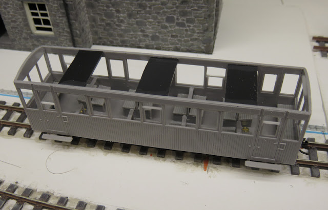
A relatively easy pick this week is this Welsh Highland coach from Dundas, which I figured would make a good preserved-era observation coach to run on Hexworthy. The kit is good quality and went together well, with just a little flash on the bogie mouldings that was easily cleaned. The instructions could have been clearer on how the seats went together, but I figured it out in the end. I decided not to fit glazing first as the instructions suggest - as that would make painting a real pain - but I can see cutting the glazing to fit each window will be the most fiddly part of the build.


As you can see I did "open" some of the drop-frame windows by cutting away the upper part of the frame and gluing in a piece of microstrip at the part-open level. This isn't hard to do and gives the coach life. The day after assembling the body I found the sides bowing in already, so added some strengthening from 40-thou plastic, though I can see they won't help the fitting of glazing!


Underneath the bogie securing nuts work loose quickly and will need fixing with glue. I'd prefer to see a captive nut in the floor myself. I trimmed the step support slightly to ensure plenty of bogie swing, and fixed Microtrains couplings to the floor with a piece of packing. As the couplings pivot and are sprung they work well body-mounted.


Another kit from the pile assembled, and awaiting the paint shop!

Sunday, 4 August 2019

Brown & Sons

My plan with the challenge layout is to frame the scene with buildings. Making model buildings takes a lot of time, but I was impressed with how easily the Petite Properties kit I recently built went together, using brick paper, and gave a good looking model. So I will be using a few more kits from the Petite Properties range on this layout, and have started by ordering three different warehouses.


The warehouses are close to the tracks so it is important to see how they fit before proceeding too far. I've started with Brown & Sons, which will hide the exit to the traverser. The laser-cut MDF parts fit together accurately, and are assembled with PVA.


The problem is the kit has a solid back and floor, but I need the building to cover the traverser when it is furthest forward. It wasn't hard to cut away the floor and part of the back wall with a piercing saw, so that there is space in the ground floor to clear the trains.


The building shell is placed on the layout to check clearances and how it looks. Although a low-relief building I have used the waste part cut from the back to make the upper part of the left-hand wall appear to be full depth.


Another view showing how the exit track might be disguised. I decided to raise the warehouse slightly to improve clearance for the trains, and as there will be a track in front of it and I wanted the floor close to rail height. A layer of mounting board was fixed under the walls, and a strip under the door lintel to lower the door height the same amount. Another layer of mounting board provides a floor to the doorway. It may get another layer of card below the scenery if required.


The shell is then covered with brickpaper over an even layer of PVA. This was printed from one of those from Wordsworth Model Railway, though I noticed when applying it the bond isn't correct for an older building. Shhh. There are some odd lines through this print too, but I don't think they will be noticeable. The window openings are cut out and folded back around the openings, but the arched tops will be stone.


The detailing parts from the kit are laid out ready for painting - stuck to a piece of card with double sided tape so I don't loose them! There are stone trim strips but only for the front of the building, I cut pieces for the end walls using part of the roof - I'll be making a new roof - and scored them to represent stone blocks. I took the opportunity to part open one of the doors too.


So that one is ready for the paint shop, and needs a roof making. I'd like some of the buildings to have a rendered finish, so have been experimenting with techniques to represent it using pieces of foam-board. As you can see I've tried pepper, sand, and talcum powder sprinkled onto PVA glue.


To compare them better they've been given a coat of grey paint (though a grey-brown would bee better). Each has a slightly different texture, I'd be interested any any thoughts...