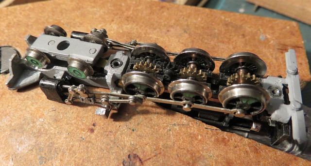
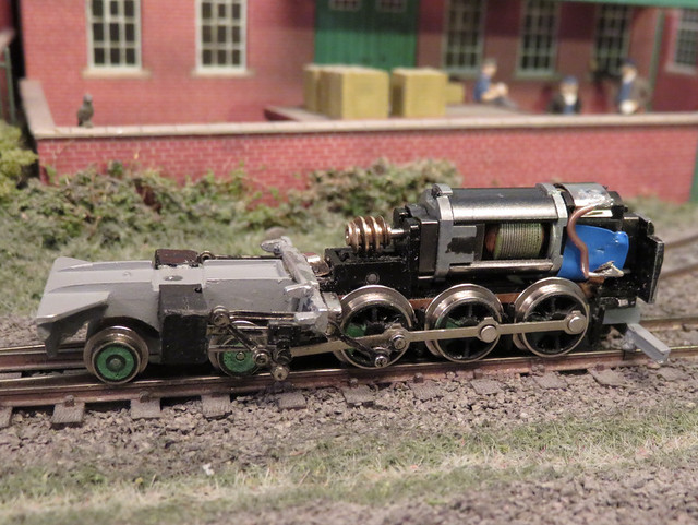
- The centre driving wheels were fractionally smaller than the others. This works fine, except that I'd managed to swap them to be the front set during the rebuild - leading to the loco rocking and poor pick-up problems
- The axles are linked by idler gears, with a little slack. However the wheels are linked with coupling rods, with a little slack. This makes it extremely difficult to assemble the chassis with the wheels quartered and the idler gears in place - and if one wheel is one tooth out, it may look OK but will bind
This left me stuck and somewhat down about the project. After all it would be a pretty difficult spare part to get, and really meant a complete set of valve gear was needed, so the project was shelved. However. a week or so back I was given another chassis by Martin Collins at a Sussex Downs group meeting. It was sans pony trucks, and he said it didn't run well (though he may have been trying to make me feel better about cannibalising it), but it did have complete valve gear, so I set about the transplant.
The first challenge was reassembling the chassis after removing the wheels to get the broken crank pin out. After the previous attempts, this time I knew I had to get the wheels and gears in mesh so the crank-pins aligned before fitting the coupling-rods. Sounds easy, but there's enough slop in the gears to make it not quite clear when they are aligned, while moving one axle meant one of the other axles or idler gears popping out - still, it only took a couple of hours this time.
I noticed a couple of differences with the replacement chassis, apart from the motor being mounted vertically. The return crank/pin was made from the same stuff as the rest of the valve gear, possibly steel, and not cast from mazak or cheese or something. Also the eccentric rod that attached to the return crank was, at it's other end, slotted to move back and forth on a pin, rather than being jointed to a representation of the rocking die link. That saves a piece and a riveted joint, while the machined crank pin was probably more robust, so I guess this is a later "improved" (cheaper and stronger) version of the chassis.
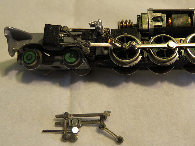
Here we have the new valve gear fitted, with the old gear below - note the extra link top right. But I still had binding, so much adjustment was carried out with the motor disconnected from the gears, rolling the chassis to detect any issues, and after some time I identified several causes:
- The slotted end of the eccentric rod could hit the crosshead if the piston was at the rear of its travel while the return crank was at its closest point of rotation. This meant setting the position of the return crank so the eccentric rod was further back, and tweaking the angle of the end of the slide bar so they didn't hit..
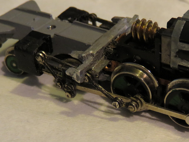
- The slotted end of the eccentric rod could hit the whitemetal cast outrigger that supports the valve gear at the upward end of it's movement. Careful filing of the casting was required, it now being rather thin at that location, along with care in positioning the valve gear assembly.
- If the slide rods are too far forward the slotted eccentric rod came to the end of it's travel and jammed, too far back and as well as that the wiggly bit (technical term) hanging from the crosshead pulled taut and jammed
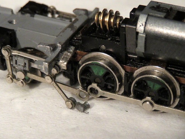
Close-up you can see how the bracket at the end of the slide bars sits on a ledge at the back of the cast cross-member, with the filed out slot for the slotted eccentric rod. Compare to the photo at the top of the page with the "original" valve gear.
Finally I have an assembled chassis that appears to work without binding. It could do with some lubrication and extra weight seems to help the pick-ups,and of course the motor grinds away in the Minitrix way, but I'm hopeful I'm back on track...
