The Sussex Downs 009 group are building a new layout, and I seem to have got the job of wiring it up, possibly because no one else seemed to want to. After some time thinking and planning I have adopted my usual approach of coding the wires, and using lots of terminal blocks, hopefully making it easier to follow - and debug in future. However, it became apparent that progress during fortnightly meetings was rather slow, so I brought home the control panel for some homework.

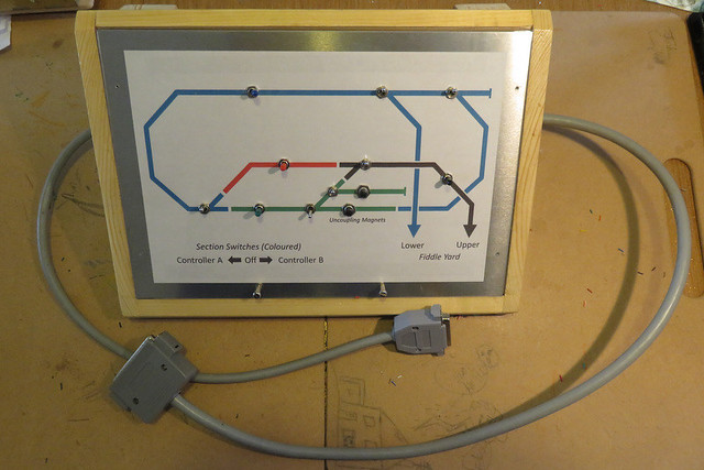
I can take no credit for the box itself as that is the work of Martin Collins, who has much better woodwork skills than I. The panel is my usual approach of a sheet of aluminium, with a computer printout schematic diagram, and a layer of clear plasticard on top. The coloured switches operate the track sections while the silver ones operate the points. The two grey cables run one to each of the two baseboards.

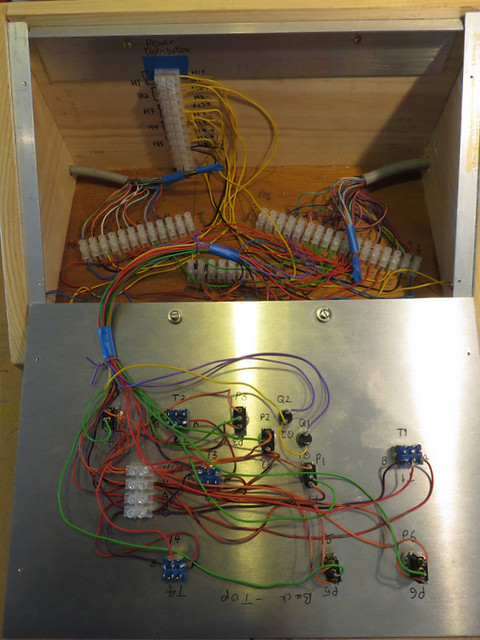
Inside (the panel is upside-down in front of it's box) may look messy, but the terminal blocks are labelled according to wire codes, and simply link the switches to the track, point motor, or appropriate power supply, so should not be too hard to follow. The incoming power connections have yet to be made, and the big cables need some kind of cable grip.

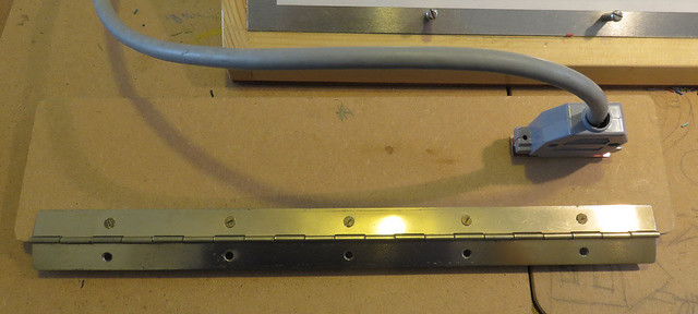
The multi-way connectors weren't much fun to wire up but I've not found a better alternative for this many pins, that isn't too bulky or costly. Each connects to a hinged panel on the back of the baseboard, one of which is seen here.

The back of the panel has more terminal blocks - which connect from the socket to the various parts of the layout. The seemingly random letters and numbers are the codes for each wire, the wires are colour coded according to purpose too. This panel will hinge down for easy access if required.
No comments:
Post a Comment