Thursday, 29 May 2025

Rail200 - Buildings in progress

In my trip to Gaugemaster to get the track for the layout, I also picked up the Wills double road engine shed kit. Well, it's called a "Craftsman kit", what you get is a pile of sheet material and some plans... really it's more of a "scratch-aid" kit. 


From another perspective, it's quite good value when you look at the quantity of Wills building materials you get. Those arched windows with the (almost) cut-out walls are nice, and there are useful details such as shed doors. I don't want to build a double-road saw-tooth roof engine shed, but the materials can be used for different buildings in a similar style...


So I built an engine shed. Single-road and with a pitched roof, but the side walls use the arched window openings and the same panelled wall as the kit, I used the plans as a guide for dimensions. The kit windows and doors will be fitted after painting. The pitched roof with off-set door is a nod to the shed at Whittingham hospital.


I opted for a corrugated iron roof rather than the slates in the kit, partly because the Whittingham shed had a replacement roof in wiggly tin, and partly because it will add a bit of variation between potentially similar building styles. The vent chimneys are from the kit, although they are provided as essentially a strip of plastic with some faint cut marks so it wouldn't have been much more work to scratch build them. 


The far end wall is just a sheet of black plastic as it will be against the backscene. The rear wall is slightly longer than the front, and the roof ends at a slight angle to meet the backscene. 


Here it is in place on the layout. The offset door minimises the wiggle needed in the track on approach, while allowing space for a workbench. Ending against the backscene suggests that it could be longer, and the track could pass through into a fiddle yard in due course. The shed is about ready for painting, perhaps it could do with gutters and downpipes and I've yet to work out how to fit the doors. 


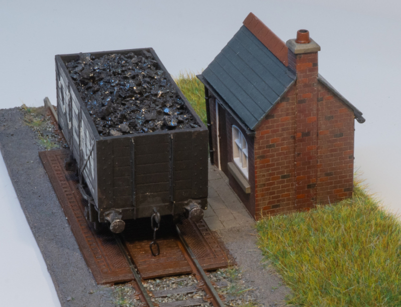
At the other end of the layout, cereal packet engineering has been adopted to plan the buildings. In the corner will be a boiler house or power house, with a siding into it for coal wagons. While it will be a similar style to the engine shed, I plan to change the details so it doesn't look like another engine shed. To the left of it I imagine part of the hospital buildings, or perhaps an outbuilding, used for "goods inwards", storage, or a workshop, it will have a small unloading platform in front of it as well as a siding entering it. It might end up looking like a generic industrial building, and it's difficult to do much given the constrained width and height. In the foreground is the placeholder for the small platform for staff and visitors, I'm still not quite sure what this will look like. 

A top view shows how the buildings will frame the scene and create the "courtyard" effect, yet not crowd the scene or hide too much track. I'm still seeking inspiration for the middle background, other than rising ground and a few trees.

Monday, 26 May 2025

Rail200 - "First fix" wiring

This morning's job was to attach wires to the tracks. Holes were poked through the foamboard into the holes in the ply below, and wires passed through.


The ends were stripped, bent to a shape that should fit into the web of the rail, and tinned with solder. At the same time, the rails were soldered to the copper-clad strips at the board end.


The wires were then pushed into place and the iron and more solder added, creating a solid joint, but being careful not to dwell with the iron too long to melt the plastic sleepers or foamboard below. 

Underneath, the wires were run back to a terminal block. I've labelled all the holes and the terminal block connections with which wire (for which track section) goes where, it helps in the future when I'll have forgotten what goes where. I used short lengths of wire stapled to the baseboard to hold the wire runs, the ends are twisted together around the bundle of wires. 

And that will be it for now. I'm not sure where I'll put the control panel/switches, the placement of the longitudinal ply support means my preferred location in the fascia isn't going to work. I've not decided if I'll fit point motors, or try manual control - dowels across through the ply sides might work well, but would need point frog switches. In any case, the deadline for entry requires a photo of the layout, and there's no requirement for it to be a working layout anyway. So, given limited time, I'll focus on completing the scenic side and can worry about wiring (along with a fiddle yard, uncoupling magnets, and other operational stuff) later. It's a bit back-to-front for me, as usually I'd make sure everything is working well before moving on with scenic treatment, but needs must!

Sunday, 25 May 2025

Rail200 - Tracklaying

One of the images in the book about the Wittingham railway shows the train passing by a pond in the grounds of the hospital, with the water just a foot or so below the track. I had an idea how I could include a similar situation in my small layout...


With the jigsaw set to cut at an angle (about 45 degrees) I cut the edge of the pond away from the front of the layout, the size being limited by the cross-member which is inset a couple of centimeters. 


The same piece was then glued back in place, the width taken out by the saw blade means it now sits 2-3mm lower than the baseboard. 


The "fixed" track at the front is to be placed on a strip of wood, which is about 3mm thick. I wanted the rest of the track at the same level, I'd planned to use foamboard but the normal stuff is 5mm thick and raised it too high. I found some 3mm foamboard on Amazon in A4 sheets, so these were cut to fit and marked out with the key track plan features and where holes would be required. The outer layers of this thin foamboard are very thin - like paper - so it is quite fragile at this stage. 


The strip of wood for the front track was stuck in place with double-sided tape, which means after the challenge I can pull it up easily and relay in Code 75 with a point - adding a layer of the thin foamboard. The set-track straight was glued down onto the wood strip with PVA. 


Holes were then cut or punched through the foamboard for the point tie-bar linkages and frog wires, and the points lined up. The rest of the track was then cut to size and fitted. I cut the rail with Xuron cutters, clean up with a file, and open out the chairs on the sleepers with a scalpel where the fishplates need to sit. Isolating fishplates were used where required around the points, I find these can be trimmed back to prevent a big gap in the sleepers. 

At the right-hand end the rails were cut flush with the edge for later connection to a fiddle yard. I found an offcut of 3mm MDF to make a solid base the same thickness as the foamboard, and a couple of pieces of PCB were cut to make a secure fixing. These were glued down, and having been pre-drilled, track-pins (the fatter Hornby type) were hammered in down to the ply base. The rails will be soldered to the PCBs shortly. Note the "fixed" track stops short with the space to the edge of the board clear as per the instructions.


So, that's the track all laid then!

Monday, 19 May 2025

Rail 200 challenge - getting started

With the plan decided, final adjustments to the positioning of the points was made - with a layout this size a few mm either way can make a difference to how the layout works.


The straight track here is offcuts of code 100, I've yet to cut any track. The medium radius point on the front track was in stock from a previous aborted project, I could use a small radius here but medium matches the 3-way and fits. It won't be fitted until after the challenge anyway. 


Track positions and key marks such as holes for point tie bar operation were pencilled onto the board. I've also thought about anywhere I might want an uncoupling magnet - I'm not sure what couplings I'll use yet, not having used OO for a long time, but the previous aborted project had used Kadees so they are most likely. I need to look into NEM fitting Kadees for more recent acquisitions though. 


I then drilled the holes and used the jigsaw to cut out openings at the possible magnet locations. Magnets won't be used at all of these - it will depend what couplings are used and where works best - but easier to cut openings now! 

I found a strip of 6mm MDF about 160mm wide and long enough to form a backscene along the rear and both ends. The height limit for the challenge is 140mm above the baseboard surface, so I cut the backscene boards to 139mm (to be safe - my cutting tolerances aren't perfect!). Holes were marked and cut out for all the tracks, in case any are extended in future. 


I found some small section strip wood and cut small blocks to support the backscene - the rules say any backscene must be fitted within the perimeter of the board. The blocks were glued down 6mm from the edge, then screwed. Then the backscene boards were screwed onto them from the outside. 


Small screws were used to join the corners - a delicate job screwing end-on into 6mm MDF, but it worked. If desired in future, the whole backscene will be removable by taking out these external screws, and could be replaced with a taller one.


I still have a tin of very pale blue paint, picked up cheap in B&Q dirt cheap as an excess of someone's colour mix and was used for Loctern Quay. A quick couple of coats and it's done. 

Sunday, 11 May 2025

Rail200 plans - decision made!

After playing with lots of paper templates, thinking things through, and discussing with friends, things became clear. Given the short timescales I really should choose a plan that is simple to build, and doesn't need complex buildings from scratch - and the 009/OO exchange siding plan fits that brief and works well. However. the idea that had really grabbed me, and seems to interest others too, is the hospital railway...


Here's my inspiration. The small book at the top shows the quirky electric line at Hellingly hospital, the two pictures at the bottom are Calderstone, and the photos on the pages in the middle all show Whittingham. Each have their charm, but it is the yard at Whittingham that has inspired the plan the most - a 3 way point leads to an engine shed and a couple of sidings in a courtyard. Common features seem to be a boiler house, stores, engine shed, and often a platform for staff and visitor trains. Some received ambulance trains during WW1. Although the hospitals covered large sites with lots of buildings, the focus of the railways is often hidden away in a cramped corner.


Despite the small space, the plan captures many of these elements, feels cramped without (hopefully) being overcrowded, and promises interesting operation too. I hope it will work scenically too, although it will need several bespoke buildings to fit the site - which puts the pressure on time!

I wasn't able to make a start this weekend, but yesterday I did manage a trip over the Gaugemaster to stock up on the track and most of the materials I think I'll need. Don't get excited by the double-road engine shed kit - it won't be built like that!

Tuesday, 6 May 2025

Rail200 plans and decisions

The next question is what to build for the Rail200 challenge. The "standalone" option allows a lot of freedom, and certainly a lot could be done in my usual 009 scale. However, I've built many micro-layouts in 009 of similar size (Loctern Quay's dimensions are almost identical) or smaller (shoebox?). O14 would be possible too, but I don't have time for track building. Anyway, my reason for taking part is because of the uniqueness of the challenge, and so the "modular" category which allows entries to be joined appeals. I'm not normally a great fan of modular layouts, but in this case I'm looking to build a scene that works on it's own (with a fiddle yard attached as needed) as well as for the one-off challenge - and that makes the challenge interesting. Also, I've a small collection of OO gauge industrial locos awaiting an excuse for a layout. 


My first thought is combining 009 with OO in an exchange yard, inspired by this scene where the Southwold railway (3' gauge) met the standard gauge, as well as places such as Minffordd, Dinas Junction - many NG railways had an exchange yard of some kind. 


PLAN 1a therefore has the NG entering (top right) from behind an exchange shed, with a siding into the shed at a raised level alongside a standard gauge siding, and another siding which drops down to the level of the SG siding (or even slightly below) for loading of coal into the NG wagons. The SG line passes the front, with a short platform for a halt, behind which the NG head shunt is set into the approach lane. Trees will probably be used to hide the exit tracks. There's room for a couple of cottages behind. I like this plan a lot, it doesn't appear too crowded and the angled NG line, lines at different levels, and scope for background scenery give the potential for an attractive scene. The downside is limited operating potential - yes the NG sidings can be shunted but even with fiddle sticks off to the right there's little meaningful operation of the SG.


PLAN 1b is the same, with the addition of a run-round loop for the NG. In theory this adds operating potential, but I'm not sure this is worth the trade of space as it feels cramped, and the SG has no more interest.


PLAN 1c has the exchange shed swapped to the left hand end, and the SG siding extended the length of the board. Hang on you say, why the point to nowhere? Well, after the challenge the through track could be lifted, and re-laid with a point to form a crossover, and so half a run-around. This gives the SG a little operational interest, including passenger services to the platform (now at the front). The NG is set slightly higher and squeezes in a short loop, spur into the exchange shed, and a siding dropping down to SG level tucked in front of the shed. There's little space for scenery except some trees along the back, and a footbridge linking the NG and SG (perhaps an unofficial passenger NG train is run?). 

Another idea for mixing NG and SG is a loading facility where minerals of some kind are transferred from NG to SG wagons. I'm not sure what minerals yet, and whether the loading operation could be depicted somehow (I've done wagon loading/unloading in 009 and O14). 


PLAN 2a has a mineral transfer in the top-left corner, I envisage something clad in corrugated iron with the NG line entering at a higher level - 5 to 6 cm above board level. The NG line runs across the back and over a level crossing, with a possible spur for a spare loco or stock, though it doesn't really have any operational interest. The SG has a couple of sidings, one under the loading chute with a weighbridge too, and passes under the road bridge to exit. Y points save space, and a connection to the front line could later form a loop. 


PLAN 2b is much the same for the SG, but moving the weighbridge makes space for a run round loop on the NG, potentially increasing operational interest but again at the price of appearing more cramped - especially as the NG will have to sit on a tall wall above the SG. 


PLAN 2c has a similar NG layout to 2b but with a different SG plan. The 3-way saves space and makes a more logical loop (when connected to the front line). This allows the middle siding to be used for an engine shed, and a short platform to be added along the front. This probably allows the best operational interest, but still looks quite crowded. The simpler NG layout of 2a could be used.

While I like the split-level layout of these plans and the mineral transfer is logical, they seem crowded and the limited height limit (14cm) for the challenge could be a problem - no space for trees on the high level for example. I don't really have inspiration for whatever the mineral might be or how it's transferred, but open to suggestions.

The final set of plans abandon the 009, and are inspired by hospital railways such as at Whittingham and Hellingly (beautifully modelled by Phil Parker), or a small industrial line such as Corringham, which had short trains, varied goods, and limited passenger services. The scene is the back end of a hospital/factory complex with a boiler house and general goods platform, a small engine shed (for small engines), and a short, narrow platform (possibly with a canopy). By contrast, the surroundings are playing fields and open countryside.  This is actually an idea I've been toying with for a while.


PLAN 3a has the two sidings to the rear, and a kick-back to the engine shed. Again, a point added later into the front line completes a loop. The left end would represent the back of the hospital, with a loading platform served by ground level doors. The boilerhouse siding could be up a short, steep gradient - it would look more interesting, but could be a pain and would only rise about 1cm. All these plans have the narrow platform along the front, a canopy could disguise the left hand exit while a water tower or tree hides the right exit. 


PLAN 3b is similar, with a Y-point used for the engine shed spur. 


PLAN 3c swaps the engine shed to the left and has the boiler house siding disappearing into the rear. This makes it very short - 1 wagon - unless it extends through the backscene! It does make more space rear right for some scenic interest, perhaps a bowling green or workers' cottages. 

I like these hospital layouts best for operational interest, with the extra point in the front line and a suitable fiddle yard there is a proper operational layout. They could also look interesting. Perhaps the biggest challenge will be time - I've less than 5 months of some weekends, a few evenings, and the odd day off if I'm lucky - so I need to keep it simple. Bespoke buildings take time, and these plans need bespoke buildings to work! On that basis, plans 1a-1c work best as they only need one special building (the transfer shed) which could be quite simple. 

Decisions, decisions! Let me know what you think...

Monday, 5 May 2025

Rail 200 challenge

To mark 200 years of railways, Peco have launched a micro layout/diorama competition. For £30 posted you get the baseboard kit, a length of track, and it comes in a large cardboard box that can be used to store/ship the finished layout. It seems these have proved popular as the first batch of 200 sold out within days, and several more batches have been release (probably as fast as the supplier can make them!). Now, I didn't order one straight away as I don't really need another layout, but I do enjoy a challenge and it seemed a shame not to take part...


The flat-pack baseboard is laser cut from good quality 9mm ply. The straight track to use for the through track of the "modular" category, or you can build any scene you like and enter the standalone category.


Assembly is straightforward, the four bracing pieces slot into the underside or onto the ends of the board with a little PVA. There were just a couple of splinters to file off but the parts are cut with great accuracy and the fit is precise.


One of the ends had a slight bow (see the gaps in the slots). I don't have a big enough clamp to hold it while the glue dried...

...so I drilled a pilot hole and put a countersunk screw to hold the end tight to the deck. I also put one into each side beam (bottom left and bottom right) in case pulling in the top allowed the bottom to move out, and for good measure three screws the opposite end to match. These may not be necessary, but assembly including the screws was no more than 30 minutes. 

Now I just need to decide what to build. I've doodled a few plans, of which more later, but here's some of the inspiration that may be used...

Friday, 2 May 2025

Railway wagon weighbridge

If it's been a bit quiet on here lately, it's because of organising the group exhibition at the end of March and some prep of my layout for it, plus a couple of magazine projects. This month's BRM features one of them, a railway wagon weighbridge from a Ratio kit.


This new kit uses a mixture of laser-cut wooden parts for the weighbridge itself, which includes a surprising level of detail, and an injection-moulded plastic hut. There's even a short length of Peco set-track which is used in the weighbridge deck. 


As you can see, it makes a nice model which would make an unusual feature on a layout.