Pages

Tuesday, 17 June 2025

Rail200 - hospital buildings

More progress with the buildings. Having completed the engine shed, at the other end of the layout I wanted to represent the hospital utility buildings, a stores/goods inwards and a boiler house/bunker. The cereal-packet mock-ups have helped check the overall size and placement, and decide the key dimensions. 


As with the engine shed, Wills building sheets are the main material including more from the Craftsman engine shed kit, although brickwork and arched windows are from extra packs. I hadn't realised the Craftsman kit had stretcher bond brickwork, but the additional pack of arched windows and extra brickwork I'd bought were English bond. No, I don't suppose anyone will notice, but I'll try and stick to the same bond for any building!

The usual techniques are used - score and snap straight cuts, drill and fretsaw out windows and curves, and use a big file to square or chamfer ends. Not forgetting to nick the courses into the exposed edges at windows and raised brickwork.


Thanks to the mock-up, it wasn't too hard to mark and cut out the pieces like a jigsaw.


With the parts assembled, including raised brick trim and arches, the façade starts to take on the character of a Victorian municipal building. I've also added a goods platform to the front. The upstairs windows used those in the arched windows set, the ground floor has doors made from planked plastic and a window from a Dornplas set.


The height restriction left little choice for the roof. No space for any kind of pitched slate roof, but a flat roof didn't seem right. I had just enough space for a very shallow pitch metal covered roof, lead perhaps, which was simply made from plastic sheet, microstrip seams, and rod ridge. Brick capping comes from the Wills building details set. Note the off-cuts bracing the corners and the black plastic floor to hold the shape. 


In place on the layout, showing how the door is just large enough for a railway wagon, with the goods platform outside. Next up, the boiler house, which thanks to the location against the backscene, only has two walls...


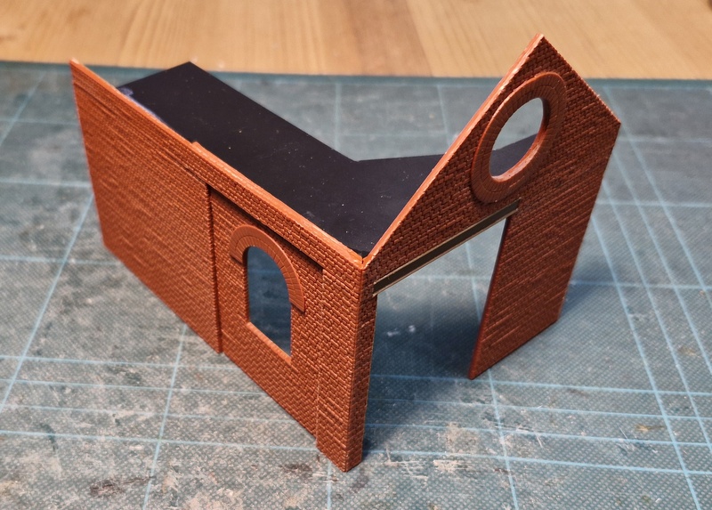
There's another arched window, a big door to use the Craftsman engine shed doors, and to add a bit of interest, a circular vent in the gable. You'd think just 2 walls makes it easy, but there's so little holding it together at the corner it was quite tricky to assemble, and there's not much holding it square!


The roof would have been really difficult without the mock-up, which I could take measurements from. The result is a reasonably neat fit against the backscene. Balancing it on the two walls is a bit tricky...


Together on the layout the buildings have different shapes and sizes to make them more interesting, but share a common style. I'm pleased with how the buildings have progressed so far, they can absorb a lot of time and will be a key aspect of the layout, using the Wills sheets and arched windows has enabled reasonably rapid progress. A few details remain (downpipes, fitting of doors) and of course they have all yet to be painted. 

Saturday, 14 June 2025

Track painting

Painting track is a bit of a tedious job but makes the world of difference to the realism of the layout. Fortunately, this is a very small layout - albeit rather packed with track.

Although I often use acrylics these days, I used enamels for the rail sides, I think they're likely to stick better and be harder wearing. The colour of rails can vary but they tend to be a dirty brown with an orangey-red tint, but rarely orange, as they are coated with a mix of deep rust, brake dust, and dirt thrown up from the ground and ballast. Here I mixed Humbrol colours in a small jar, with just a drop of thinners to help the mix flow. The brush is run along the rail sides coating both the rail and the rail fixings on the sleepers, including points but not where blades meet stock rails.


The 3-way point had the rails diverging to the disconnected route painted on their tops too, to reflect them being out-of-use. Excess paint is wiped of the rail top with kitchen towel, and when dry, a fibreglass stick is used to properly clean the rail head. 


The shiny sleepers need toning down too. Sleepers seem to be a grey-brown colour, so I mixed cheap artists acrylics - white with a drop of black and brown for a pale grey-brown. I used a cheap stiff flat brush - meant for kids, but even a 4-year old would find this one poor quality - filled with paint but with the excess wiped off on the palette. It's not dry brushing, which takes ages, but using a stippling motion angled towards the rails I applied the paint lightly. This leaves some of darker brown plastic showing through and the grain effect is highlighted, and allows the paint to be pushed around the rail fixing leaving that rusty brown. You can see from the paint left on the board surface the light stippled application. This proved to be relatively quick and quite effective.

While working on the track I cut away some sleepers from within the engine shed, and cut out the 3mm foamboard within it, to give the impression of an inspection pit. This was painted dark grey-black to make it look deeper than it is, along with the gaps between the sleepers where they will be under a floor so white doesn't show in the flangeways. 

Sunday, 1 June 2025

Wessex NG Modellers Open Day 2025

Yesterday the Wessex Narrow Gauge Modellers held an open day, a rather smaller affair than the Narrow Gauge South exhibition held by the same group on "even" years. However, the community hall venue had two rooms allowing a good number of 009 (and HOe/HOn30) layouts as well as the 009 Society sales stand and a trader. It was also an appropriate location for a community of like-minded modellers to meet, with lots of chatting going on.

The first layout I saw was Nic Arthur's Bowcombe. I've liked all of Nic's layouts and this one is no exception. The subtle scenery and detailing create an atmospheric scene.


Back to the 70's by Tim Ticknell takes an old Cyril Freezer "rabbit warren" track plan and makes it work while looking natural and plausible, and unmistakably Welsh. I love it. 


David Marshall helped his grandson Daniel to build Harringford, he said the Inglenook track plan was partly influenced by Loctern Quay. It reminds me of my son's layout Slugworth, built when he was 11, which also used adapted Metcalf kits. Viewers were invited to have a go at the shunting puzzle.


Saith Ar Hugain by Christopher Payne is built in a plastic storage box, and shows a delightful layout can be built in a very small space and easily stored.


Wissey Creek by Stuart Reeve captures the Fens with a lovely composition. 


Julian Evison's Selborne, which was built as part of a group modular scheme, but is cleverly designed to work just as well as a standalone layout.


Richard William's Gemto: Ikkehavn is a quirky layout set on an island between Denmark and Norway. Richard demonstrated that like my layout Hexworthy, despite having just four points, the layout can hold four trains...


East Quay by John Niblett


A couple of modules of the "Freem009" modular layout by the Wessex NG modellers.


Devil's Bridge by Andy Cundick, the well-known prototype modelled in the early 1900s.


Kaninchenbau is a computer-controlled slice of the Alps by Iain Morrison. Since the trains move apparently at random, I was quite lucky to capture 5 in one shot!


A great day out and I do hope it is repeated in future. 

Thursday, 29 May 2025

Rail200 - Buildings in progress

In my trip to Gaugemaster to get the track for the layout, I also picked up the Wills double road engine shed kit. Well, it's called a "Craftsman kit", what you get is a pile of sheet material and some plans... really it's more of a "scratch-aid" kit. 


From another perspective, it's quite good value when you look at the quantity of Wills building materials you get. Those arched windows with the (almost) cut-out walls are nice, and there are useful details such as shed doors. I don't want to build a double-road saw-tooth roof engine shed, but the materials can be used for different buildings in a similar style...


So I built an engine shed. Single-road and with a pitched roof, but the side walls use the arched window openings and the same panelled wall as the kit, I used the plans as a guide for dimensions. The kit windows and doors will be fitted after painting. The pitched roof with off-set door is a nod to the shed at Whittingham hospital.


I opted for a corrugated iron roof rather than the slates in the kit, partly because the Whittingham shed had a replacement roof in wiggly tin, and partly because it will add a bit of variation between potentially similar building styles. The vent chimneys are from the kit, although they are provided as essentially a strip of plastic with some faint cut marks so it wouldn't have been much more work to scratch build them. 


The far end wall is just a sheet of black plastic as it will be against the backscene. The rear wall is slightly longer than the front, and the roof ends at a slight angle to meet the backscene. 


Here it is in place on the layout. The offset door minimises the wiggle needed in the track on approach, while allowing space for a workbench. Ending against the backscene suggests that it could be longer, and the track could pass through into a fiddle yard in due course. The shed is about ready for painting, perhaps it could do with gutters and downpipes and I've yet to work out how to fit the doors. 


At the other end of the layout, cereal packet engineering has been adopted to plan the buildings. In the corner will be a boiler house or power house, with a siding into it for coal wagons. While it will be a similar style to the engine shed, I plan to change the details so it doesn't look like another engine shed. To the left of it I imagine part of the hospital buildings, or perhaps an outbuilding, used for "goods inwards", storage, or a workshop, it will have a small unloading platform in front of it as well as a siding entering it. It might end up looking like a generic industrial building, and it's difficult to do much given the constrained width and height. In the foreground is the placeholder for the small platform for staff and visitors, I'm still not quite sure what this will look like. 

A top view shows how the buildings will frame the scene and create the "courtyard" effect, yet not crowd the scene or hide too much track. I'm still seeking inspiration for the middle background, other than rising ground and a few trees.

Monday, 26 May 2025

Rail200 - "First fix" wiring

This morning's job was to attach wires to the tracks. Holes were poked through the foamboard into the holes in the ply below, and wires passed through.


The ends were stripped, bent to a shape that should fit into the web of the rail, and tinned with solder. At the same time, the rails were soldered to the copper-clad strips at the board end.


The wires were then pushed into place and the iron and more solder added, creating a solid joint, but being careful not to dwell with the iron too long to melt the plastic sleepers or foamboard below. 

Underneath, the wires were run back to a terminal block. I've labelled all the holes and the terminal block connections with which wire (for which track section) goes where, it helps in the future when I'll have forgotten what goes where. I used short lengths of wire stapled to the baseboard to hold the wire runs, the ends are twisted together around the bundle of wires. 

And that will be it for now. I'm not sure where I'll put the control panel/switches, the placement of the longitudinal ply support means my preferred location in the fascia isn't going to work. I've not decided if I'll fit point motors, or try manual control - dowels across through the ply sides might work well, but would need point frog switches. In any case, the deadline for entry requires a photo of the layout, and there's no requirement for it to be a working layout anyway. So, given limited time, I'll focus on completing the scenic side and can worry about wiring (along with a fiddle yard, uncoupling magnets, and other operational stuff) later. It's a bit back-to-front for me, as usually I'd make sure everything is working well before moving on with scenic treatment, but needs must!

Sunday, 25 May 2025

Rail200 - Tracklaying

One of the images in the book about the Wittingham railway shows the train passing by a pond in the grounds of the hospital, with the water just a foot or so below the track. I had an idea how I could include a similar situation in my small layout...


With the jigsaw set to cut at an angle (about 45 degrees) I cut the edge of the pond away from the front of the layout, the size being limited by the cross-member which is inset a couple of centimeters. 


The same piece was then glued back in place, the width taken out by the saw blade means it now sits 2-3mm lower than the baseboard. 


The "fixed" track at the front is to be placed on a strip of wood, which is about 3mm thick. I wanted the rest of the track at the same level, I'd planned to use foamboard but the normal stuff is 5mm thick and raised it too high. I found some 3mm foamboard on Amazon in A4 sheets, so these were cut to fit and marked out with the key track plan features and where holes would be required. The outer layers of this thin foamboard are very thin - like paper - so it is quite fragile at this stage. 


The strip of wood for the front track was stuck in place with double-sided tape, which means after the challenge I can pull it up easily and relay in Code 75 with a point - adding a layer of the thin foamboard. The set-track straight was glued down onto the wood strip with PVA. 


Holes were then cut or punched through the foamboard for the point tie-bar linkages and frog wires, and the points lined up. The rest of the track was then cut to size and fitted. I cut the rail with Xuron cutters, clean up with a file, and open out the chairs on the sleepers with a scalpel where the fishplates need to sit. Isolating fishplates were used where required around the points, I find these can be trimmed back to prevent a big gap in the sleepers. 

At the right-hand end the rails were cut flush with the edge for later connection to a fiddle yard. I found an offcut of 3mm MDF to make a solid base the same thickness as the foamboard, and a couple of pieces of PCB were cut to make a secure fixing. These were glued down, and having been pre-drilled, track-pins (the fatter Hornby type) were hammered in down to the ply base. The rails will be soldered to the PCBs shortly. Note the "fixed" track stops short with the space to the edge of the board clear as per the instructions.


So, that's the track all laid then!

Monday, 19 May 2025

Rail 200 challenge - getting started

With the plan decided, final adjustments to the positioning of the points was made - with a layout this size a few mm either way can make a difference to how the layout works.


The straight track here is offcuts of code 100, I've yet to cut any track. The medium radius point on the front track was in stock from a previous aborted project, I could use a small radius here but medium matches the 3-way and fits. It won't be fitted until after the challenge anyway. 


Track positions and key marks such as holes for point tie bar operation were pencilled onto the board. I've also thought about anywhere I might want an uncoupling magnet - I'm not sure what couplings I'll use yet, not having used OO for a long time, but the previous aborted project had used Kadees so they are most likely. I need to look into NEM fitting Kadees for more recent acquisitions though. 


I then drilled the holes and used the jigsaw to cut out openings at the possible magnet locations. Magnets won't be used at all of these - it will depend what couplings are used and where works best - but easier to cut openings now! 

I found a strip of 6mm MDF about 160mm wide and long enough to form a backscene along the rear and both ends. The height limit for the challenge is 140mm above the baseboard surface, so I cut the backscene boards to 139mm (to be safe - my cutting tolerances aren't perfect!). Holes were marked and cut out for all the tracks, in case any are extended in future. 


I found some small section strip wood and cut small blocks to support the backscene - the rules say any backscene must be fitted within the perimeter of the board. The blocks were glued down 6mm from the edge, then screwed. Then the backscene boards were screwed onto them from the outside. 


Small screws were used to join the corners - a delicate job screwing end-on into 6mm MDF, but it worked. If desired in future, the whole backscene will be removable by taking out these external screws, and could be replaced with a taller one.


I still have a tin of very pale blue paint, picked up cheap in B&Q dirt cheap as an excess of someone's colour mix and was used for Loctern Quay. A quick couple of coats and it's done.